Lathe RPM meter not working

Advert

Lathe RPM meter not working

Home Forums Manual machine tools Lathe RPM meter not working

Viewing 25 posts - 1 through 25 (of 27 total)
  • Author
    Posts
  • #449600
    Colin LLoyd
    Participant
      @colinlloyd53450

      I have a Real Bull Mini Lathe as supplied by Amadeal Ltd of London. The in-built RPM display suddenly stopped working. By which I mean that the display stopped working (no LEDS light) – not necessarily that the sensor wasn't working. Taking the control box off and also looking at the sensor in the gearbox end of the lathe showed no visible reasons for non- operation i.e. severed cables, burnt areas of the control board. All the rest of the lathe functions as normal. Amadeal as always were very helpful, but admitted that they were not electronics experts – but suggested possibly the 5v feed to the display was at fault. And it's true that no combination of the 4 contacts on the control board supplying the display gave anything above 1.2v. The RPM display is a useful item – but not to the extent of buying a new control board. I could just provide an external 5v supply to the display – but without knowing which of the 4 pins provides power – this might do more harm than good. Alternatively I could just add an external Hall effect RPM meter to the lathe – sonething that I have already done to both my Amadeal Milling machine and my Woodworking lathe. Does anybody know the circuit diagram for the control board of these types of lathe – or at least the functional pin-out of the RPM display cable.

      Advert
      #13764
      Colin LLoyd
      Participant
        @colinlloyd53450

        Probable loss of 5v supply to RPM display of Mini lathe

        #449625
        Steviegtr
        Participant
          @steviegtr

          If it is the same as most of the rpm meters it is usalyy the 1st 2 connections that are the + & – connection. Google it & ask for wiring diagram for ??? Is this any good.

          Regards.

          Steve.

          real bull.jpg

          #449628
          Steviegtr
          Participant
            @steviegtr

            I notice that R3 is a 10k resister. wonder if that is ok.

            Steve.

            #449660
            Colin LLoyd
            Participant
              @colinlloyd53450

              Hi Steve, thanks for the information and the circuit diagram . Your comment about the first 2 connections being the + & – makes sense as I was getting 1.2v between the 2nd and 3rd and same between 1st and 2nd – which means that the 2nd connection is probably positive. I will check R3 as well. Thanks again – will keep this thread informed until conclusion.

              #449682
              John Baron
              Participant
                @johnbaron31275

                On a different machine but virtually identical circuit, the 10 uf marked C5 on your diagram had gone short circuit and taken the 78LO5 regulator out. If this is the case then check the 100 mh choke as well.

                Also the 10 k resistor value is suspect, I think 1 k would be nearer the correct value !

                I=V/R, 0.0005 amp, seems low.

                #449832
                Martin Connelly
                Participant
                  @martinconnelly55370

                  John, 10k might be correct. If the sensor is very high resistance then current will flow through R3 and charge C6 untill C6 was at 5V. If the sensor then went to a lower resistance state the capacitor will discharge through it towards zero volts. This swing in voltage may be used to contribute to the sensor signal.

                  Martin C

                  #449836
                  Steviegtr
                  Participant
                    @steviegtr

                    Colin, does your sensor have a LED on it as mine does. If so & that is not lit the supply has gone down. It is from the same source as the read out.

                    #449839
                    John Baron
                    Participant
                      @johnbaron31275

                      Hi Martin C,

                      C6 is only 100 pf, not enough to hold a charge of any magnitude, more for spike suppression. C5 is the filter capacitor and will hold far more charge. Its an electrolytic capacitor and more likely to leak and fail. In theory the voltage regulator is supposed to be short circuit protected, but they do fail.

                      If C6 goes short circuit the high current flow could quite easily kill the voltage regulator. It will be interesting to hear what the OP finds.

                      #449863
                      Colin LLoyd
                      Participant
                        @colinlloyd53450

                        Thanks for all the replies. I've discovered that my machine appears to be an exact copy of the Grizzly Model G0765 – for which I've gained a comprehensive 76 page manual.

                        Specific reply – not sure if John and Martin are talking to me or to each other – so will leave that for now

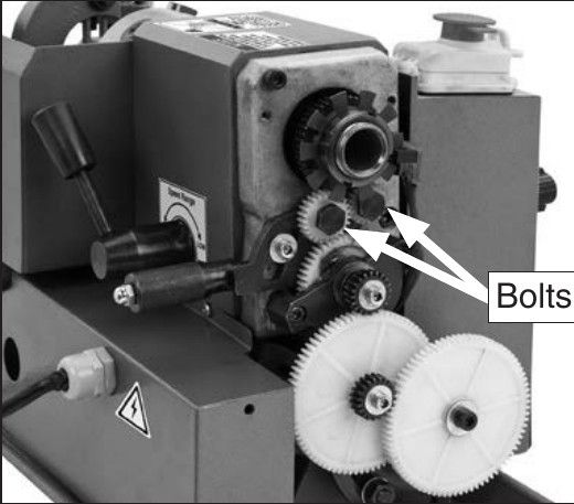
                        Steviegtr – not sure if LED or proximity speed sensor. The sensor comprises 2 cube shaped columns either side of a multi-finned disc on the mandrel end as shown in the attached photo The columns do have a thin recessed line halfway down – which could contain a small LED on one side and a detector on the other.rpm sensor.jpg

                        #449869
                        Steviegtr
                        Participant
                          @steviegtr

                          Just a thought of a cheap try it possible fix. The standard USB adaptors for phone chargers are 5v DC output. You could try & disconnect your supply to the DRO & connect one of those.

                          Steve.

                          #449876
                          Colin LLoyd
                          Participant
                            @colinlloyd53450

                            Steviegtr – that's exactly what I plan to do – but unsure of which of the 4 wires going from the Circuit board to the Digital Readout are the +5v and Gnd lines – I don't want to blow the entire control board by getting this wrong. From my initial post – it looks like wire 2 is +ve and either 1 or 3 is Gnd – but not sure. Failing everything else – I've found a youtube video that shows how to put a hall effect sensor chip (of which I have several) and a rare-earth magnet onto the timing belt lower pulley. There again I could do the same onto the spindle behind the chuck – and link up to external Digital Readout unit as I have done for my milling machine.

                            #449890
                            John Baron
                            Participant
                              @johnbaron31275

                              Hi Colin,

                              Can you post a picture of the control board ?

                              Alternatively do you have a multimeter and can you identify the voltage regulator. If so identifying the connections should be straight forward.

                              PS, you have a slotted vane with a photo optic sensor.


                              Edited By John Baron on 30/01/2020 19:13:07

                              #449933
                              Stuart Smith 5
                              Participant
                                @stuartsmith5

                                Colin

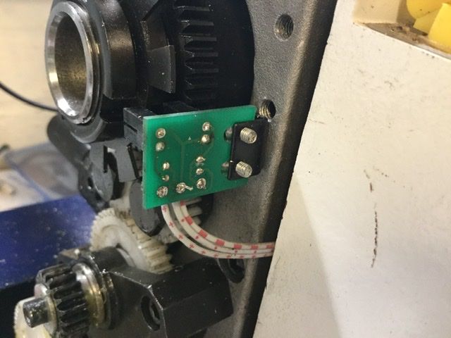
                                I have the same lathe as you. I have taken a photo of the opto sensor board and measured the voltages.

                                a2fb67fa-891b-438b-b7d1-b5325af7b23c.jpeg

                                As you can see, the cables are marked with a '+', a dot and a long dash (left to right) . I have confirmed that they are + 5 volts, ground, and output (left to right again).

                                Output is about 5 volts when power is on but lathe is not turning. ( the output is biased to 5 volts by a 10 k resistor on this board.) It is pulled down by the sensor when detecting pulses. With the lathe turning, I measured the dc voltage using my multimeter and it was about 2 volts and dropped as the speed was increased. This would be a simple check if you don’t have access to an oscilloscope.

                                There are 2 resistors on this board. The top one ( nearest the sensor) is 10 k and is connected between + 5 volts and the output to bias the output high ( ie to 5 volts). The bottom one is 300 ohms and is the current limiting resistor in the feed from the 5 volt supply to the LED of the sensor.

                                I don't know if this is any help, but at least you will know what to expect at this board.

                                I don't think that the diagram posted by Steve earlier can be the power supply circuit for this type of speed sensor as this would not provide enough current for the LED with a 10k resistor in circuit.

                                I am going to be dismantling my lathe in the next few days to change the gears and bearings, so if you don't resolve the problem by then I can measure the volts and take some photos on the circuit boards on mine.

                                Stuart

                                #449935
                                Stuart Smith 5
                                Participant
                                  @stuartsmith5

                                  Colin

                                  Just an extra point to my previous post, with the lathe on but not rotating, the output is just under 5 volts when one of the vanes is between the sensor and about 1.3 volts when a space is between the sensor.

                                  Stuart

                                  #449951
                                  John Baron
                                  Participant
                                    @johnbaron31275

                                    Hi Guys,

                                    That makes sense, the opto device is the same as can be found in almost any printer made. From memory the LED in them requires around 5 ma which would mean that the PSU shown has the wrong value for the 10 k resistor if that is the correct circuit diagram.

                                    If the wiring markings are as shown in the picture, is shouldn't be difficult to trace them back to the PSU.

                                    #449966
                                    Les Jones 1
                                    Participant
                                      @lesjones1

                                      Looking at the schematic posted in the second post the only output seems to be via the 10 K resistor. This would not provide enough current to power the tachometer electronics. I suspect the 10 K resistor is the load resistor for the optical sensor. (If it does use an optical sensor.) There must be some other source of power to the tachometer. For us to be able to help you you will need to provide some more information. Does it use an optical sensor or some other method ? Can you post pictures of all the circuit boards in the lathe and the speed sensor so we can get an idea of how the low voltage to the tachometer is supplied ? Can you include pictures of the component side and the etch side of the auxiliary control board so we are sure it is the same as the one posted.

                                      Les.

                                      #449969
                                      Stuart Smith 5
                                      Participant
                                        @stuartsmith5

                                        Colin

                                        Correction to my previous post, typo crept in . Should be :

                                        With the lathe on but not rotating, the output is just under 5 volts when one of the vanes is between the sensor and about 0.13 volts when a space is between the sensor.

                                        Stuart

                                        #449971
                                        Stuart Smith 5
                                        Participant
                                          @stuartsmith5

                                          Colin

                                          On the Amadeal website, there is a photo of the display board they sell as a replacement for the mini lathe.

                                          The connections are marked on the board in the photo as 5v, GRD, PL and PE.

                                          If this is the same board as yours this may help.

                                          Stuart

                                          #450046
                                          John Baron
                                          Participant
                                            @johnbaron31275

                                            Hi Guys,

                                            On my machine the slotted opto sensor gets 5 volts to both the LED and detector via a 1.5 k resistor directly from the voltage regulator. The output to the speed display comes from the top of a 1 k resistor connected between the detector output and ground.

                                            HTH.

                                            #450080
                                            Colin LLoyd
                                            Participant
                                              @colinlloyd53450

                                              Thanks Guys for all the input. You will have to be a bit patient as I go through all these useful ideas and suggestions. While no electronic engineer – I know how to use DVM and oscilloscope (although I only have a PC operated HANTEK). I will let you know of my findings.

                                              #450159
                                              I.M. OUTAHERE
                                              Participant
                                                @i-m-outahere

                                                https://www.amadeal.co.uk/acatalog/DRO-.html
                                                I got this off the amadeal site and it shows the pin markings , looking at the rear of the dro the connector pins from right to left are 5v, gnd , and the two wires to the opto sensor in the link below 

                                                https://www.amadeal.co.uk/acatalog/Sensor-Cable-for-CJ18-12A5-IC1-334.html#SID=13

                                                I would disconnect the opto sensor as well when testing your voltages as it may have died and be pulling the 5v rail down .

                                                Please be careful poking around in there with the power on , it only takes a slip and it can be lights out for you !

                                                That schematic is not the official one it was drawn by a guy on another forum
                                                https://madmodder.net/index.php?topic=6980.0

                                                There is a link to it in the first post .

                                                In the documentation it states that some values may not be correct so that 10K resistor could be 100R or 1k .

                                                As Les mentioned it would be best if you can take a few pics as he may pick up on something you didn’t , maybe a bulged top on an electrolytic capacitor that will indicate a dead or leaky cap that will pull the 5v rail down . It is just a simple linear regulator and you may have troubles with a switchmode power supply like used for phone chargers or wall warts as they can be noisy and play havoc with the display .

                                                Edited By XD 351 on 01/02/2020 01:15:53

                                                Edited By XD 351 on 01/02/2020 01:17:53

                                                #451170
                                                Stuart Smith 5
                                                Participant
                                                  @stuartsmith5

                                                  Colin

                                                  Did you manage to sort out the problem?

                                                  I have taken the control box off my cj18 lathe to change the gears and bearings. The circuit is simpler than the one in an earlier post and is labelled with the 5v, GND and signal connections. There is no resistor in the 5v feed to the speed sensor or display. Let me know if you still need help, I can draw up the circuit diagram. 

                                                  Stuart


                                                  Edited By Stuart Smith 5 on 07/02/2020 22:42:06

                                                  #451373
                                                  Colin LLoyd
                                                  Participant
                                                    @colinlloyd53450

                                                    Hi Guys – sorry about silence – but a few other jobs have got in the way. I tried to supply 5v to the Digital display – but without success – perhaps the digital display board itself is the culprit. In the meantime I have added a magnetic proximity unit to the gear cover with a small rare-earth magnet on one of the vanes of the rotor. This seems to work fine – although it does mean another wall plug for the supply. I will continue to investigate – but the immediate problem i.e. not having a digital RPM meter has gone away.

                                                    Stuart – one of the first jobs I did was to exchange the bearings for angular contact bearings – although I was advised (too late) to actually install taper bearings. I also did an experiment on the effect of pre-loading on the temperature increase in the bearing housing – see the following

                                                    https://www.model-engineer.co.uk/forums/postings.asp?th=130430

                                                    #513676
                                                    Stephen Packer
                                                    Participant
                                                      @stephenpacker65140

                                                      I've got the same lathe… and the same problem.

                                                      I've done a little fault checking and the regulator's definitely dead.

                                                      However, removing the display unit and supplying 5V to it doesn't cause it to light up and when the inputs to the display are 5V, Gnd, pulse sensor, pulse sensor I would have expected just 5V and Gnd should have resulted in a '0' display.

                                                      The capacitor across the regulator output and ground seems to be OK so I'm at a bit of a loss why the regulator died and suspect it could have been the display board (although it drew negligible current from my bench power supply).

                                                      I'll have another look tomorrow but will replace the regulator and see what happens; I don't really want to buy a new display board if I can avoid it!

                                                    Viewing 25 posts - 1 through 25 (of 27 total)
                                                    • Please log in to reply to this topic. Registering is free and easy using the links on the menu at the top of this page.

                                                    Advert

                                                    Latest Replies

                                                    Home Forums Manual machine tools Topics

                                                    Viewing 25 topics - 1 through 25 (of 25 total)
                                                    Viewing 25 topics - 1 through 25 (of 25 total)

                                                    View full reply list.

                                                    Advert

                                                    Newsletter Sign-up