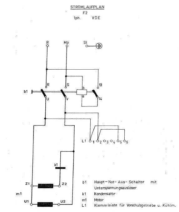
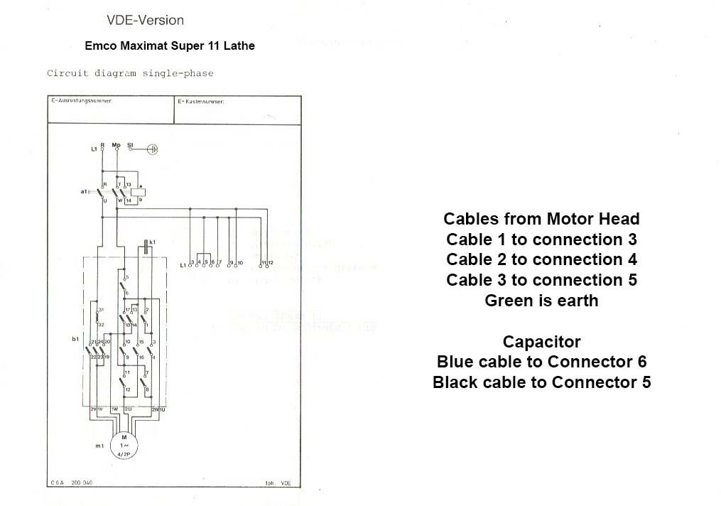
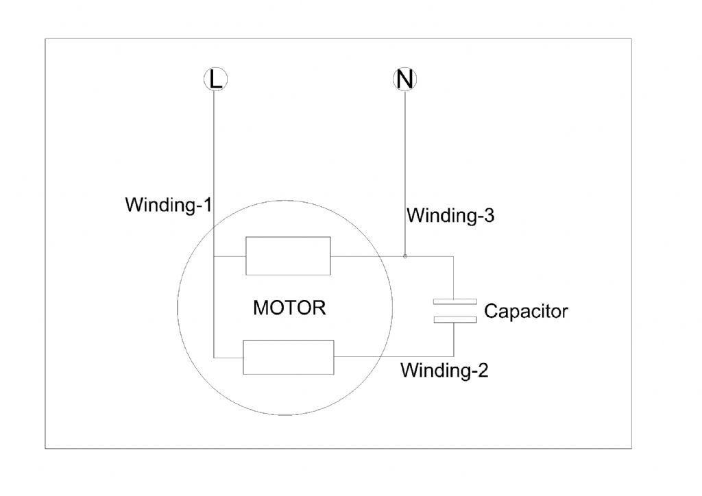
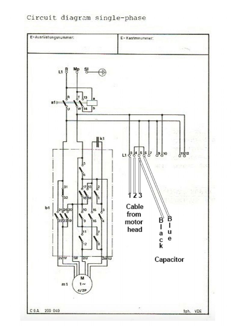
Help with Electrics on Emco FB-2 Milling head/table
Help with Electrics on Emco FB-2 Milling head/table
- This topic has 15 replies, 6 voices, and was last updated 27 June 2020 at 16:07 by
CheeHui Chin.
Viewing 16 posts - 1 through 16 (of 16 total)
Viewing 16 posts - 1 through 16 (of 16 total)
- Please log in to reply to this topic. Registering is free and easy using the links on the menu at the top of this page.
Latest Replies
Viewing 25 topics - 1 through 25 (of 25 total)
-
- Topic
- Voices
- Last Post
Viewing 25 topics - 1 through 25 (of 25 total)


