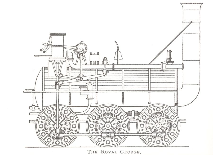
I have long been interested in pre-Victorian locomotives so my next project will be a 3 ½ inch scale live steam “Royal George”. This was Timothy Hackworth’s loco of 1827; a significant machine in the early development of steam traction. However as I am sure you can imagine being such an early engine design sources and records are scarce and open to interpretation. I am trying to initially produce a set of working drawings and am hoping that forum members would be kind enough to give me the benefit of their opinions and expertise on some of the more puzzling aspects arising from the surviving documents. I hope to build it as close as is reasonably possible and feasible to the locomotive Hackworth initially designed and built.
I have T R Pearce’s excellent book on the locomotives of the Stockton and Darlington Railway. This contains the earliest surviving sketch of the loco and Alan Priors conjectural drawing. Unfortunately neither is on the net so unless you have the book are not readily available!
However 2 of the main surviving illustrations are available here
Source 1 and here Source 2
In addition Hackworth’s “Sans Pereil” (1829 0f Rainhill fame) survives as a ‘hulk’ at Shildon and also as a full scale working replica. It might perhaps help to throw light on some features of Royal George built only a couple of years earlier. The net has numerous sites in which this engine is mentioned – for example – ans_Pareil_Replica_05-09-17_69.jpeg”>Source 3
or simply type Sans Pereil into an image search – Source 4
Perhaps some of you have actually seen it in real life.
Finally Hackworth built a small model of the loco
photos here – Source 4
After all that (!) here is my first ‘problem’ –
The pistons do not appear to have the conventional piston rod guides/slides/crossheads. The drawings show an inverted V under the cylinders. Sans Pereil has a more conventional arrangement, and it is hard to imagine that the Royal George relied solely on support from the stuffing box/gland to maintain the piston rods parallel motion to the cylinders. Source 2 shows the V with no apparent linkage at its base; source 1 appears to show some kind of connection?
Is it a bracket with a brass bush set into the bottom of the V to allow supported vertical movement of the piston rod or is part of the linkage mechanism as well? Or am I missing the point completely?
Your opinions would be very welcome
Many thanks
Martin
Half centre.


