Equatorial Platform Build

Advert

Equatorial Platform Build

Home Forums Clocks and Scientific Instruments Equatorial Platform Build

Viewing 21 posts - 1 through 21 (of 21 total)
  • Author
    Posts
  • #472431
    Neil Wyatt
    Moderator
      @neilwyatt

      This new project is going to have some interesting challenges, as it will combine woodwork, metalwork, 3D-printing and electronics.

      A 'Dobsonian telescope' has a robust but simple mount but it only works in alt/az (altitudue /azimuth) so it isn't an easy task to track things in the night sky.

      The usual solution is a platform you can place it on which uses widely spaced bearings in the shape of part of a cone with its axis aligned with the pole star.

      Typically the design allows about 15 degrees of rotation – enough to track for an hour without resetting.

      These can be arranged to correct pointing errors for long exposure photography, but more usually are simply synchronised sufficiently to follow objects for visual observing or short exposure photography (e.g. planetary imaging).

      I'm planning a platform to take my 10" scope with an angle of 52 degrees, so that with minor adjustment it will be suitable for anywhere in the UK – even Scotland if propped up an inch or so.

      Designs for the South bearing vary from a very simple 'pin in a depression' to a second conic section like the North bearing. I've decided to use a robust pin that's a push fit in a pair of ball races to give a secure but easily demountable solution.

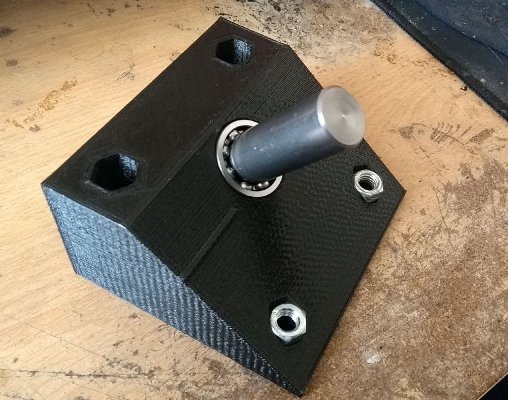
      A nice combination of 3D printing and turning:

      mystery object.jpg

      Very chuffed with the fit – pushes in without shake

      I got some chatter when parting and had to follow my own advice of increasing the feed rate!

      The nuts are M8 and fill is at 40% so this is a pretty solid chunk of plastic.

      The pin will be glued into a suitable socket on the base board.

      Neil

      Advert
      #3878
      Neil Wyatt
      Moderator
        @neilwyatt

        Multi-disciplinary construction!

        #472570
        Steviegtr
        Participant
          @steviegtr

          Looks like good work you are doing.

          By the way Niel I spoke to the friend with the Telescope today. It is a Meade LX600 12" reflector with Starlock. Means sod all to me.

          Steve.

          #474072
          Neil Wyatt
          Moderator
            @neilwyatt

            I've made the sectors, 3D printed with aluminium rails held on by printed clips and clear gorilla glue.

            Gathering together the other bits, including a stepper and an Arduino Nano.

            Trying to 3D print pulleys for a 1.5mm pitch timing belt I found in my bits box.

            Using a 0.1mm nozzle to get decent 1mm-diameter grooves, but this has made it prone to warping so the big one ius proving tricky. I tried a raft and it just peeled up at one side. A brim work with the smaller pulley so trying that with the bigger one.

            The maximum tension is going to be about 11 kilos or 25lbs (40ncm stepper through a 7mm diameter pulley), interesting to see if it works as it will make setting up easier than using gears. Final ratio will be about 10:1 so should be enough to move a telescope weighing about 30kg.

            Neil

            #474073
            Neil Wyatt
            Moderator
              @neilwyatt
              Posted by Steviegtr on 17/05/2020 23:44:19:

              Looks like good work you are doing.

              By the way Niel I spoke to the friend with the Telescope today. It is a Meade LX600 12" reflector with Starlock. Means sod all to me.

              Steve.

              It's a nice big Newtonian scope, will give spectacular views under darker skies

              Neil

              #474549
              Neil Wyatt
              Moderator
                @neilwyatt

                Some pictures for an update:

                This is a 100-tooth pulley for the 1.5mm pitch belt.

                This is the upper platform, pivot at one end angled at 52 degrees, sectors at the other angled at 38 degrees. Distance from pivot arranged so that, as it turns the sectors will stay in contact with a pair of rollers.

                Next job is to design and print the two rollers to support the sectors, one of which will be free, the other driven by a stepper. This is a rig up to let me measure the height and angle for the rollers (do you see the little card triangle?) I decided not to rely on trig…

                The larger piece of ply will end up being the base, with arrangements for levelling/tilting it to get an exact polar alignment.

                #480591
                Neil Wyatt
                Moderator
                  @neilwyatt

                  An update!

                  I've had a rethink!

                  The problem with the angled sectors is that although they have a simple, circular cross section is it makes the positioning of the support/driving rollers critical. I found that this made getting a good drive to the sectors difficult, and a slight twist (just a couple of mm) in the board was enough to make a difference.

                  I'm also wary that the PLA could 'creep' under a sustained angular load despite the hefty design.

                  The elliptical design avoids this by having a vertical load but needs long rollers as the contact point moves in and out.

                  An ideal design MIGHT be to make the sectors part of the surface of the 52-degree cone so they track across the same point like my original angled sectors, but can use almost horizontal rollers angled in line with the pivot point.

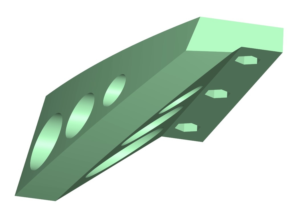
                  Hard to do in wood without a 3D jig but easy in CAD. The front curve of this new runner follows the same curve as my MK 1, but instead of havinga steeply angle rolling surface it has an almost horizontal one. It also means the upper surface can be supported by the upper board, even though the fixings will be set back. Importantly, as the load will all be acting vertically that small twist in the board effectively becomes irrelevant as the position of the rollers is no longer critical. Instead of having to set them so the sector falls at the right place on the roller, the roller can be made over-length without any criticality in positioning. Finally, almost all the weight of the scope will be keeping the roller in contact with the sector instead of about 60%:

                  1944092444_NewRunner.jpg.97e40dc4e9ad569dde657347523c2f25.jpg

                  The downside is that it means the aluminium strips may not be feasible. I can get a decent surface finish without steps using careful orientation and support material (on a non-working surface). Any residual irregularities will, hopefully, be too small to cause problems and partly compensated by give in the rollers.

                  #480592
                  Neil Wyatt
                  Moderator
                    @neilwyatt

                    The sector is normally modelled on a section through an imaginary cone with its axis pointed at the pole and its lower edge horizontal. To create a bearing surface, the sections are typically extended into short prisms of constant cross-section.

                    A section at 90-degrees to the cone axis is circular.

                    • Its contact point (where you would place a roller) is stationary as it rotates (convenient, allows rollers to be compact).
                    • Its bearing surface is angled to match the elevation of the pole star (awkward, and easy to lose position/drive).

                    A vertical section is elliptical.

                    • Its contact point moves towards or away from the pivot (cone apex) as it rotates (awkward, requires longer rollers).
                    • Its bearing surface is horizontal (convenient).

                    My idea is for the section at 90-degrees to be extended as a short truncated cone – a true slice of the imaginary cone.

                    • Its contact point is stationary (convenient).
                    • Its bearing surface is close to horizontal (horizontal at lowest point, a few degrees for practical sector designs) (convenient).
                    #480593
                    Neil Wyatt
                    Moderator
                      @neilwyatt

                      these are the new rollers. You can see they are a much simpler shape and how the 'new' sectors allow them to be horizontal. Instead of a precise location, they just need to be placed in contact with the supported and unloaded platform and slightly angled to get line contact and avoid any risk of the sector hitting the box.

                      1849046161_Newrollerboxes.thumb.JPG.7951ec2012256d47576e999161d8af25.JPG

                      I've decided to stick with the simple 5: ratio for now,as slightly smaller rollers will give me a step size of about 0.016m and I suspect that for a simple platform rather than a precision engineered mount a resolution smaller than this is pointless.

                      At my sector diameter of 788mm, one arc-second is almost 0.002mm, so I will have 8 arc-seconds per step, 550 milliseconds per step.

                      Obviously these are best estimates to be fine tuned in use. I will be able tune to +/- 0.2% using the millisecond counter in Arduino.

                      The new parts fill the old upper platform but it doesn't take advantage of the extra surface on the new sectors:

                      790214718_NewSectors.thumb.JPG.46afbfd3ea678b1360a314350b3ea2f1.JPG

                      I'm going to make a new platform, with a more rounded shape that will also allow me to move the pivot point further forward again. I will be getting close to the axis through CofG ideal by accident rather than design!

                      I've just got to wait for some ball races to replace the ones I lost for the tension idler.

                      #480595
                      Neil Wyatt
                      Moderator
                        @neilwyatt

                        So… while waiting for the ball races, I've started work on a 3D printed box for the control board/display which will be an Arduino Uno with a 16×2 LCD shield.

                        I think the irony is that the most complex turned part is going to be a special threaded spindle to hold the tension idler for the toothed belt!

                        Newil

                        #480598
                        Joseph Noci 1
                        Participant
                          @josephnoci1

                          Nice Neil! Quite amazing how model making is changing – so many technologies and disciplines are becoming easily accessible , each of which just open up new ways of doing things, which in turn enable the next level up…. You are certainly getting your monies worth wrt the 3D printer!

                          Keen to see this mount assembled and driving..

                          Joe

                          #482773
                          Neil Wyatt
                          Moderator
                            @neilwyatt

                            Hi Joe, yes… but I hate to see how fast the reels fo PLA disappear!

                            Well… the last few weeks have been a crash course in C++ which I always said I wouldn't bother with. Fortunately it's not too far removed from other languages especially the assembler I'm used to which uses most of the same concepts/operators.

                            I'm still trying to figure out if there's a convention for when you use upper and lower case letters… why is it true and false but HIGH and LOW? and String() when every other data type or conversion starts with a lowercase letter?

                            So where am I?

                            I have an all-new set of sectors and rollers but need to remake the upper platform.

                            I will need feet, two of which at least are adjustable for polar alignment.

                            I need to refine the control box and also print some bracket/boxes for the limit switches. I've actually used small (good quality) push buttons rather than microswitches as exact repeatability isn't needed. The main change to the control box will be adding a housing for a little piezo sounder.

                            Quite pleased with the control system so I'll summarise it:

                            Arduino Uno with a16x2/buttons shield I've had in a draw for a few years.

                            Stepper driven via a DRV8825 in 32 microstep mode. The ~12mm diameter roller rotates in about 37 minutes, but this will no doubt have to be tuned, software allows for this. Then limit switches and sounder.

                            Starts up and makes a pretty close approximation of a BBC Micro beep smiley

                            If eeprom is untainted it stores the default microsecond and millisecond delays for three rates (sidereal, solar, lunar).

                            Then loads these values into RAM.

                            Then loads up sidereal rate and starts tracking.

                            When in track mode it displays the rate and delay length to 0.1ms (default is about 68ms). Also up down arrows to show what to press to change the delay in 0.1ms steps.

                            A mode select button cycles through track and three other modes. Tracking continues unless overidden by another movement.

                            Next mode is to choose the rate, just cycles through the three and pause.

                            Move mode has up and down buttons to make small movements (will need fine tuning) to help with centring an object in RA or polar aligning.

                            Left and right buttons get the platform to move to the end of travel as determined by the limit switches. When 'homed' it starts tracking again, but f it reaches the other end it just stops unless manually moved off the limit switch.

                            Final mode is the clever bit, you can save the current rate into eeprom as a new default, or you can restore the default for the current rate from eeprom. A third button allows you to restore the 'factory' values if you have totally muddled them up. Unlike the other modes which are 'sticky' this one shows a brief confirmation message then drops back into tracking.

                            Other refinements are a 'beep' on saving data or hitting a limit switch.

                            So quite excited really and looking forward to building it all up in time to catch Saturn and Jupiter as they approach opposition, and, of course, Mars later in the year.

                            #482797
                            SillyOldDuffer
                            Moderator
                              @sillyoldduffer
                              Posted by Neil Wyatt on 28/06/2020 20:01:04:

                              Hi Joe, yes… but I hate to see how fast the reels fo PLA disappear!

                              Well… the last few weeks have been a crash course in C++ which I always said I wouldn't bother with. Fortunately it's not too far removed from other languages especially the assembler I'm used to which uses most of the same concepts/operators.

                              I'm still trying to figure out if there's a convention for when you use upper and lower case letters… why is it true and false but HIGH and LOW? and String() when every other data type or conversion starts with a lowercase letter?

                              Early C was criticised as being a 'Macro Assembler on Steroids', which is true enough to be a good thing! It's a low-level language, much easier to maintain than assembler, but close to the machine and fast and memory efficient.

                              There's method in the naming madness. By convention macros are named in CAPITALS, thus HIGH and LOW in Arduino are macro definitions, not part of of the language. Macros are often used to define constants. Knowing they are macros is useful when code is ported to another platform because HIGH and LOW might be different; an Arduino is nothing like Intel. If the hardware is different it's only necessary to change the macro definition and recompile.

                              In C, strings are character arrays terminated by a binary zero. Again, they're not part of the core language, instead they're manipulated with a set of standard library functions with names like strcpy(), strcmp(), strcpy(), strdup()

                              C++ is a super-set of C mainly supporting objects but also with many new built-ins. One of these is a full-blown String type, which is part of the language. So C has strings, while C++ has strings and Strings. By convention, objects, are defined with a leading capital. All capitals indicates a constant or a macro. In C++ true and false are also part of the language, associated with bool which is a C++ primitive type, not an object. Clear as mud!

                              In C:

                              char s[8]; // Buffer of 8 characters

                              strcpy( s, "hello" ); // OK 6 chars in total

                              but

                              strcpy( s, "hello world" ); // Explodes! Buffer too small, programmer mistake

                              In C++

                              String s;

                              s = "hello"; // OK

                              s = "hello world"; // still OK because String allocates memory automatically

                              strings are super-fast, efficient and dangerous, Strings are safe but slower and use more memory. On a small computer where memory is short and speed might be vital, as on an Arduino it's useful to have the choice and to know which is which.

                              Strings and/or strings, an equatorial mount is an excellent Arduino project.

                              Dave

                              #482983
                              Neil Wyatt
                              Moderator
                                @neilwyatt

                                > Clear as mud!

                                No, you do make sense (belkieve it or not!)

                                > an equatorial mount is an excellent Arduino project.

                                I must say C++ makes it very, very easy to keep adding features, discovered my 'shield' has the potential to control the backlight using PWM but they botched the circuit by wiring the output direct to the base of an NPN transistor so it is effectively grounded when high! Also found out how to modify it (add a current limiting resistor) and worked out where, took longer to sort than to program a little routine for variable brightness.

                                So… today I've printed the final iteration of the control box with room for the sounder (the base is printing now) and just put a coat of varnish on the lower and (new) upper platform.

                                Thanks,

                                Neil

                                #483278
                                Neil Wyatt
                                Moderator
                                  @neilwyatt

                                  I've just done a test, using a leisure battery instead of the telescope. Not as heavy, but placed right at the front to put all the weight on the rollers and way below the CofG so much less balanced.

                                  All went well, except near one extreme (probably beyond the range I actually need) it stalled but the motor current was limited at only about 200mA, I upped it to 400mA and it worked perfectly. The stepper is a 900mA one so I've got plenty of headroom if needed.

                                  Left to sort:

                                  • Adjustable feet (printing one now)
                                  • limit switch arrangement.
                                  • Properly wiring up
                                  #484096
                                  Neil Wyatt
                                  Moderator
                                    @neilwyatt

                                    The Platform in action!

                                    #484104
                                    SillyOldDuffer
                                    Moderator
                                      @sillyoldduffer
                                      Posted by Neil Wyatt on 05/07/2020 15:44:58:

                                      The Platform in action!

                                      Very good! And all up and running quickly. Are you providing the musical accompaniment as well? It's all very talented.

                                      Dave

                                      #484119
                                      Neil Wyatt
                                      Moderator
                                        @neilwyatt
                                        Posted by SillyOldDuffer on 05/07/2020 16:11:15:

                                        Posted by Neil Wyatt on 05/07/2020 15:44:58:

                                        The Platform in action!

                                        Very good! And all up and running quickly. Are you providing the musical accompaniment as well?

                                        The guitar is my brother I did the bass and drum machine, a very long time ago…

                                        #484128
                                        SillyOldDuffer
                                        Moderator
                                          @sillyoldduffer
                                          Posted by Neil Wyatt on 05/07/2020 16:52:44:

                                          Posted by SillyOldDuffer on 05/07/2020 16:11:15:

                                          Posted by Neil Wyatt on 05/07/2020 15:44:58:

                                          The Platform in action!

                                          Very good! And all up and running quickly. Are you providing the musical accompaniment as well?

                                          The guitar is my brother I did the bass and drum machine, a very long time ago…

                                          A surfeit of talent. LBSC never designed and programmed an equatorial mount, 3D printed any parts, or made a full colour documentary video with a professional quality home-made sound track, before publishing it where billions of fans could all watch it for free.

                                          Technology marches on! Despite the silver lining, there will be 100% cloud cover every time you want to point it at a planet.

                                          smiley

                                          Dave

                                          #484131
                                          Neil Wyatt
                                          Moderator
                                            @neilwyatt
                                            Posted by SillyOldDuffer on 05/07/2020 17:06:52:

                                            A surfeit of talent. LBSC never ..

                                            Look what he did do, basically took live steam and made it a hobby for everyman.

                                            I'm sure he would have had a field day with new tech (and found plenty to heap scorn on!)

                                            Neil

                                            #484402
                                            Neil Wyatt
                                            Moderator
                                              @neilwyatt

                                              Tried it out last night… this is my report copied across from an astro forum:

                                              I managed a test last night, this is an edit of my post in the 'what are you doing tonight' thread after sleeping on it.

                                              Main conclusion- too much stiction on the dob part, I need to make it smoother! Not really an issue with the platform, I think I need to dose it with silicon polish at the very least. It moves in jumps and the minimum AZ move is often nearly a full FOV at ~30mm and getting a target centred at 5mm took forever! Alt is much better but not perfect, although if unbalanced it can move on its own.

                                              As for the platform, PA was easy, at least to the suggested approach of getting Polaris in the finder and adjusting until it stayed still during a slew. The polar angle must be pretty accurate as I just set everything level and the task was setting it due north. Errors were rapidly apparent so a button to stop the slew early will be welcome. My finder's cross hairs come out at 45 degrees but that didn't make the process difficult. Better PA could be achieved with a polarscope in the finder holder and getting Polaris to travel around the circle.

                                              Getting the track rate was hard. A first everything drifted off top left regardless of speed. This made me think it was running too slow. I reduced the delay down to about 15ms until the stars definitely went off the right side pretty sharpish. I then increased the delay, and eventually settled on about 64 milliseconds delay by the time clouds came in, which isn't bad given the estimate was ~68 and expected to need to speed up to allow for compression of the roller. I think the earlier problem was using Lyra which was very high and I suspect a combination of PA error and an unbalanced scope slowly moving in ALT when near vertical.

                                              It was easiest to judge movement using small stars near the edge of the FOV rather than bright ones at the centre. Next time I will use a 25mm plossl with cross hairs.

                                              Incidentally I used a Szentmartoni EP made according to a recipe on SGL that uses three small binocular objectives for about 33mm. As promised it was sharp to the edge and comfortable to use!

                                              I changed to a Skywatcher UWA 5mm to 'fine tune' the tracking rate. the sky wasn't very dark, but I went back and (just) split the double double at 300X – seeing wasn't brilliant, but it seemed to be keeping in place even at that magnification, certainly long enough for planetary imaging.

                                              Changes needed:

                                              I will wire the disabled reset button on the shield across the end limit switch. This will provide a way of interrupting a polar alignment slew, as initial drift is obvious in a couple of seconds, you don't need to wait for a full slew.

                                              I will round the default track speeds 0.1ms and keep the adjustment step of 0.1ms. The 0.1ms seems fine enough and it's annoying that all the readouts are not round numbers – and no point reading the delay to finer resolution than the adjustment. I may change the step to 0.05ms, at the expense of slowing down the tuning process a little.

                                              Although up to speed up tracking and down to slow it seemed logical, as up increases the delay and vice versa. It's confusing to press up and see a number decrease.

                                              The debounce period for the buttons is too long, as are some of the 'confirmation delays' of 1s. I will reduce both.

                                              The 'nudge RA' increment was WAY too aggressive, the briefest of presses and the view changes completely.

                                              A remote handset might be a useful addition, perhaps with a reduced set of controls.

                                              Mechanically, everything worked fine with the platform. Balance is great and I didn't even bother with a nut on the pivot bolt for the dob, so worth considering a plain pin instead. There is some wobble when moving the scope, but it isn't excessive and I didn't notice any when hands-off.

                                              Main beef is with the dob itself, I must find a way of reducing 'stiction' and counter-intuitively locking the alt movement. But my brain is already thinking of ways to add steppers and belt drive to ALT and AZ – perhaps for 2021!

                                            Viewing 21 posts - 1 through 21 (of 21 total)
                                            • Please log in to reply to this topic. Registering is free and easy using the links on the menu at the top of this page.

                                            Advert

                                            Latest Replies

                                            Viewing 25 topics - 1 through 25 (of 25 total)
                                            Viewing 25 topics - 1 through 25 (of 25 total)

                                            View full reply list.

                                            Advert