Emco Maximat Super 11 Handwheel Dial

Advert

Emco Maximat Super 11 Handwheel Dial

Home Forums Manual machine tools Emco Maximat Super 11 Handwheel Dial

Viewing 6 posts - 1 through 6 (of 6 total)
  • Author
    Posts
  • #13363
    Graham Meek
    Participant
      @grahammeek88282
      Advert
      #383561
      Graham Meek
      Participant
        @grahammeek88282

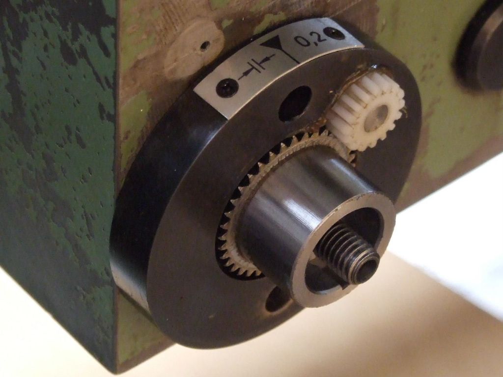
        I have had several requests for information on the above dial following my posting of the above photograph on the Forum post about Blacking solutions recently.

        I thought a few words about the modification might not go amiss. I took delivery of the Maximat in 1986. The original handwheel dial was calibrated to read 19 mm per rev. I soon got used to working with this odd number but had placed a replacement on the too do list.

        Thirty years on it was still there on the list, and following a day when I had made 3 components wrong due to my metal arithmetic not being as good as it used to be I decided it was time for the replacement.

        First thoughts were to go for a dial reading 25 mm per rev, as an imperial version could be done with 1" per rev. While I did manage such a design the dial was larger than the handwheel and the whole thing looked hideous.

        I finally settled on 20 mm per rev, although the dial was slightly larger than the original. This would be easier I thought as the gears only have to have multiples of 19 and 20 for it to be an exact conversion. That was until I actually checked the travel per revolution of the handwheel which turned out to be under 19 mm. Not a lot under, but as I was going to use a gear train I could at least get it right or nearer.

        The perfect ratio came out at a 38 tooth gear driving a 39 in a single reduction. This presents a problem as for the two gears to be co-axial then one gear has to have the PCD enlarged or the other needs to have the PCD reduced.

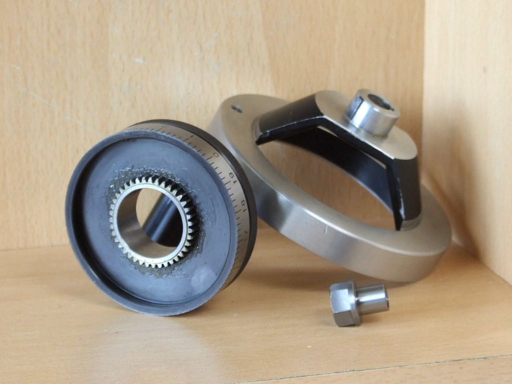
        To produce these gears by standard B&S gear cutters is not on. In Industry it is not such a problem if there is access to a gear hobber. The Home Machinist can however still make a single point cutter that will come very close to the required form. It just needs an understanding of how to draw gear tooth profiles. This then was the approach I took and the results are shown below.

        To help eliminate backlash in the system a Delrin Idler gear was used which was cut with zero backlash. Any backlash that is present is removed by adjusting the dial in the direction of travel. The assembled dial has lived up to my expectations and I am glad to report there has been no scrappers since.

        Regards

        Gray,

        fig input gear, delrin idler gear and backplate.jpg

        fig dial with 39t gear, modified handwheel and extender nut.jpg

        #384685
        Graham Meek
        Participant
          @grahammeek88282

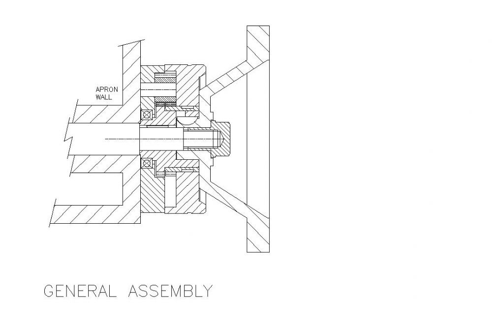
          My memory being what it is I had omitted to add the GA and the fact that I had added a ball bearing race to the assembly. This was to remove any up and down motion while operating the handwheel. The ball race makes the handwheel silky smooth now.

          Regards

          Gray,

          20 mm maximat handwheel conversion.jpg

          #384728
          Neil Wyatt
          Moderator
            @neilwyatt

            Very neat and compact, Graham.

            Neil

            #385003
            Nick Hulme
            Participant
              @nickhulme30114

              That's a lovely job.

              Would one which switched between Imperial and Metric be possible?

              #385069
              Graham Meek
              Participant
                @grahammeek88282

                During the 1970's when we were said to be "Going Metric", many companies had new dials fitted to their machines that would read either units. (Digital readouts where available at this time were restricted to JIg Borers and Jig Griders) The conversion dials I am familiar with had one dial eccentric to the main dial and this eccentric dial was driven by an internal gear. At best the conversion was a dial which had an odd dimension. An 1/8" feedscrew would have the usual 125 divisions for the Imperial dial but the Metric dial would have 3.2 mm.

                Such a conversion has an error, (3.175 actual), not very big I admit, but none the less an error, and it does nothing for the ease of moving a specific metric dimension, due to the 0.2 per rev add on. As the metric dimension has to be divided by 3.2, to get the number of turns. Any partial turn then needs to be converted from a decimal to an actual reading on the dial. From this reading the accumulated error has to be subtracted.

                More often than not the metric dimension was converted to imperial units and the standard imperial dial used in the same old way. This was easier, less prone to mistakes and it was what had been going on for many years before anyway.

                These dials were not what we today would call "High End", and in many instances they were replaced with the original dials due to swarf ingress and wear.

                While it would be feasible to make such a dial in this instance, it would give a very awkward imperial dimension. Plus I feel the average Home Machinist will not have the facilities to cut an internal gear. This would therefore limit the appeal to many people. Far better to have a dial which is in keeping with the shop measuring facilities, most of us being either imperial or metric.

                Regards

                Gray,

              Viewing 6 posts - 1 through 6 (of 6 total)
              • Please log in to reply to this topic. Registering is free and easy using the links on the menu at the top of this page.

              Advert

              Latest Replies

              Home Forums Manual machine tools Topics

              Viewing 25 topics - 1 through 25 (of 25 total)
              Viewing 25 topics - 1 through 25 (of 25 total)

              View full reply list.

              Advert

              Newsletter Sign-up