Castings, creating a datum before milling

Advert

Castings, creating a datum before milling

Home Forums Beginners questions Castings, creating a datum before milling

Viewing 19 posts - 1 through 19 (of 19 total)
  • Author
    Posts
  • #442533
    Garry Smith 7
    Participant
      @garrysmith7

      88cfe241-d12c-4116-beb2-df1068037075.jpeg79fa4fc3-a188-40be-941d-1bbfc7c5a98c.jpeg2ea08d0e-4220-4fdb-970c-f29a03b49d88.jpeg
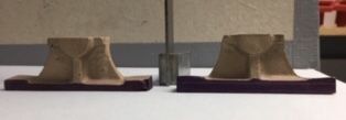
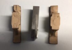
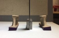
      The Above are castings of the bearing brackets for the Tina Mill Engine.

      Having practiced milling on my new mill by making basic clamps I am now ready to mill castings. Can experienced members advise me the best way to get a datum face on the castings before I set them in the milling vice. I think I need to make one face true before I start milling to give me a datum ( is this a true statement) easy simple methods to achieve this will be most welcome.

      Thanks for reading.

      Advert
      #9991
      Garry Smith 7
      Participant
        @garrysmith7

        Milling Castings

        #442534
        JasonB
        Moderator
          @jasonb

          What you really need is MEW 289 Milling for beginners that is about dealing with odd shapes and castings!

          Without the drawings and castings infront of me it's hard to be exact but I usually go over the castings with files first to remove any unwanted mould part lines etc.

          Next compare the castings to the drawing to see where metal needs to come off and how much machining allowance has been given, this will save you taking too much off the first surface and then finding you are short on the opposite face.

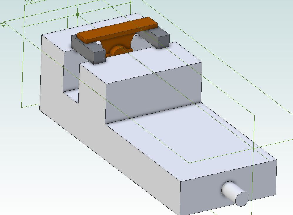
          At a glance I would make the bottom surface my datum and first surface to be machined flat (does not have to be to finish yet) I would hold in the milling vice upside down with the length of the casting along the length of the jaws, slip two equal height packets (drill bits, lathe tools, parallels) across the two jaws to support the work and set whet will be the upper bolting surface horizontal. Then mill the base flat, you should also be able to take it to width and length at the same setting.

          #442540
          Garry Smith 7
          Participant
            @garrysmith7

            Thank you Jason. Could you just confirm the third line from the bottom “set whet will be the upper “.Not sure how I know the casting would be vertical with your set up in the vice before milling. If it’s not vertical then the base would not be horizontal when milled ?

            #442545
            Martin Johnson 1
            Participant
              @martinjohnson1

              As Jason says, it all rather depends. First step is always to knock the lumps off with a file. A good next step is to mark the castings out, with (say) the base underside surface and shaft centreline. Also mark out the base in relation to it's axial position with the bearings and spot where the holding down holes will come. You will soon see where there is not enough metal (happens on commercial castings too often) and too much metal, and can adjust your marking out accordingly to get the best shot at the casting.

              I would then probably go for a preliminary cut on the under foot and the long side of the foot – not to size at first, just to give you square edges.

              On complex stuff it can be like knitting with fog to get a start. A dodge then is to cut card templates to actual size and sight them against the casting to get the best shot.

              Hope that helps,

              Martin

              #442546
              Garry Smith 7
              Participant
                @garrysmith7

                Thanks Martin, Card templates great idea I’ve used them before so must have had a senior moment not to remember them.

                #442547
                IanT
                Participant
                  @iant

                  Castings are definitely a mixed blessing Garry.

                  For your castings I'd do exactly as Jason advises and clean it up and then very lightly machine your reference surface. It's easy to assume that a casting has enough 'meat' all around and to try to get down to a clean surface on the first pass – and then you find that there is not enough left elsewhere to end up with the stated dimensions.

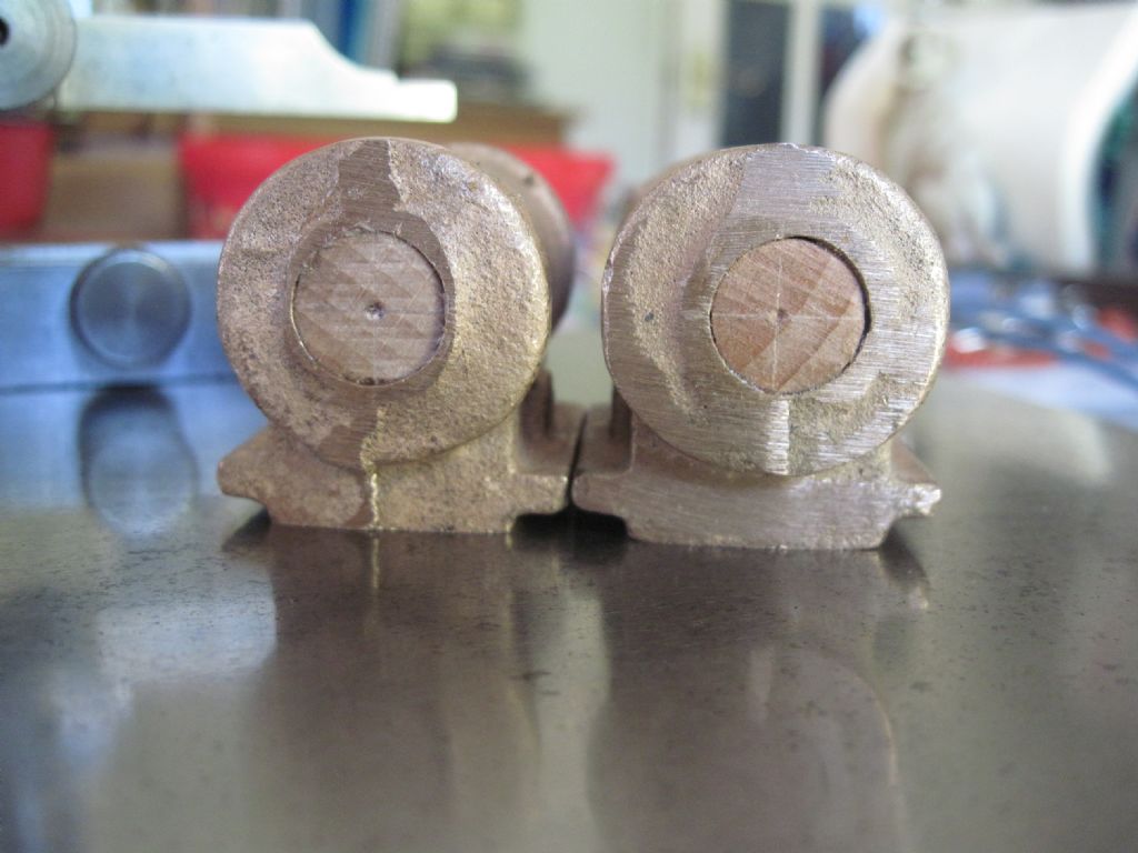
                  I've recently machined several pairs of cylinder castings for use in a published locomotive design. There wasn't enough metal to get smooth surfaces all around in either pair- so you really have to decide where to compromise or simply change the design. For these castings of yours (and any other castings involved) it will pay to look at the item "in the round" and make sure you don't have to adjust something before you start.

                  In the cylinders I had to balance the machining at each end-face because the friend I was doing them for had already ordered laser cut frames (to the drawing) and the cylinder cut-out is oversize to the available metal in the castings supplied. Both ends could have been cut back to clean surfaces if the frame cut-out could have been reduced. The design also specified a 1/2" bore but on both cylinder sets the core was already 12mm and the cores weren't central either (one cylinder was offset by nearly 3mm) so to bore & ream them to the given size was impossible.

                  The flanges need to be symmetrical to the body, so I always set-up based on those (rather than the bores). The final bore size (pre-reaming) on this pair was about 16mm & I obviously had to do both cylinders the same. I'm sure it will all pan out but with castings you really have to have a good look at them and think ahead a bit.

                  In many ways small fabrications, whilst they need more work up-front, are a bit easier when you come to actually machine them.

                  Regards,

                  IanT


                  Stirling Cylinders


                  Edited By IanT on 20/12/2019 17:25:53

                  #442560
                  Garry Smith 7
                  Participant
                    @garrysmith7

                    Thanks Ian Advice is gratefully received.

                    #442571
                    JasonB
                    Moderator
                      @jasonb

                      Something like this

                      bearing ped 1.jpg

                      #442641
                      Garry Smith 7
                      Participant
                        @garrysmith7

                        Jason thanks for the CAD drawing that makes sense to me and I will adopt it and hopefully make changes as and when other castings need it. As for MEW 289. The one month I don’t buy it there an article that would be useful to me. I can’t get one anywhere at the moment so I’m hoping I can get a back issue next month. Thanks for your time and help it’s very much appreciated as a newbi.

                        #442666
                        JasonB
                        Moderator
                          @jasonb

                          It's not out in the shops until next week, should be available in digital any day.

                          Just don't take too big cuts as the GM castings can bend, if in doubt add a support/stop behind as you will see in the mag.

                          #442670
                          Henry Brown
                          Participant
                            @henrybrown95529

                            For what its worth, and probably a bit OTT for this, we used set the parts on adjustable jacks and paint on hard blue where there was to be metal to be removed and then scribe lines where the removal was to be from. If the casting wouldn't clean up it was adjusted slightly until best match could be achieved. You might be ok using Plasicene to set the parts on but, of course you will need a surface table of a good flat surface and a scribing block.

                            #442675
                            IanT
                            Participant
                              @iant

                              Purists look away now….

                              I recall having great trouble with some bronze frame castings for a 3.5 inch NG 'Lew' many years ago (I was attending evening classes). I machined the first one and took too much metal off, so purchased a second one and did exactly the same thing again (and No, I've never met Einstein)

                              I was really 'miffed' shall we say – but Pete (one of the Instructors) said no problem and we walked over to the Welding shop and he soldered a lump of brass on it and then I was able to machine everything to size!

                              Not best practice but sometimes much better than buying another casting…

                              Regards,

                              IanT

                              #442695
                              Garry Smith 7
                              Participant
                                @garrysmith7
                                Posted by IanT on 21/12/2019 14:06:47:

                                Purists look away now….

                                I recall having great trouble with some bronze frame castings for a 3.5 inch NG 'Lew' many years ago (I was attending evening classes). I machined the first one and took too much metal off, so purchased a second one and did exactly the same thing again (and No, I've never met Einstein)

                                I was really 'miffed' shall we say – but Pete (one of the Instructors) said no problem and we walked over to the Welding shop and he soldered a lump of brass on it and then I was able to machine everything to size!

                                Not best practice but sometimes much better than buying another casting…

                                Regards,

                                IanT

                                #442696
                                Garry Smith 7
                                Participant
                                  @garrysmith7

                                  Great 👍👍👍 😊😊😊 More than one way to skin a cat.

                                  #442704
                                  JasonB
                                  Moderator
                                    @jasonb

                                    I've done the same thing Ian when a casting has been undersize, just mill a flat surface and solder on a new machining allowance

                                    #442723
                                    Dennis R
                                    Participant
                                      @dennisr

                                      Garry

                                      There was a series by Stan Bray in Model Engineer under the heading of Bray's Bench starting in Vol 176 No 4009 in 1996 about building "Tina" from the castings from GLR Kennions together with a follow on of building the boiler.

                                      Harold Hall also did part of the engine in one of his series in MEW, I think on using a milling attachment he had made.
                                      You may find some useful information in the articles.

                                      Dennis

                                      #442773
                                      Nick Clarke 3
                                      Participant
                                        @nickclarke3

                                        I have the opposite issue with a pair of 71/4" locomotive gunmetal cylinder castings. No names, no pack drill!

                                        Not got there yet, but they have no cores so I am facing drilling them out to allow a boring tool to enter, where I am worried about drills grabbing and then seeing a not inexpensive amount of gunmetal swept into the swarf bin!

                                        As I say, not got there yet, but as I write this I am wondering what is the chance that they will be very close to size on the outside dimensions to add to my cup of joy?

                                        #442938
                                        John Olsen
                                        Participant
                                          @johnolsen79199

                                          Nick, To drill gunmetal with less risk of grabbing, it would be worthwhile to stone the rake off the cutting edges of the drill. This can be done by hand with a small stone. To be clear, this is not done on the end facets of the drill, it is done on the flute so that where the drill is cutting it has zero or negative rake, rather than the positive rake that the flute gives as it reaches the cutting edge.

                                          A drill treated this way is not as good for cutting steel as it used to be, but if you can manage it, it can be good to have a few treated this way for brass and gunmetal.

                                          John

                                        Viewing 19 posts - 1 through 19 (of 19 total)
                                        • Please log in to reply to this topic. Registering is free and easy using the links on the menu at the top of this page.

                                        Advert

                                        Latest Replies

                                        Home Forums Beginners questions Topics

                                        Viewing 25 topics - 1 through 25 (of 25 total)
                                        Viewing 25 topics - 1 through 25 (of 25 total)

                                        View full reply list.

                                        Advert

                                        Newsletter Sign-up