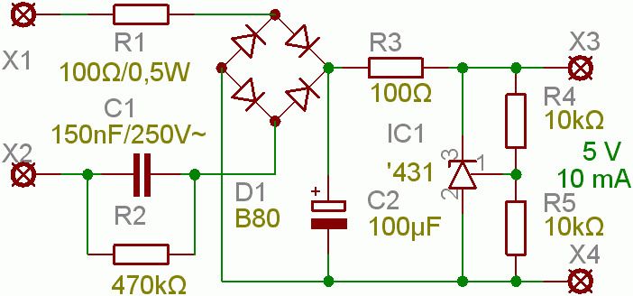
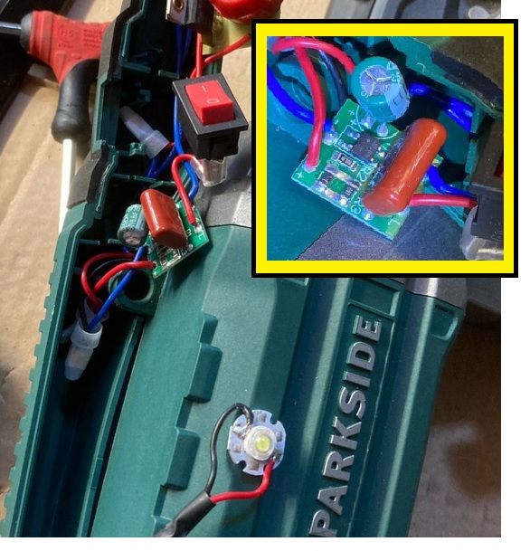
Posted by Anthony Knights on 18/08/2020 09:02:59:
… There is also (according to what I have read) a problem with distortion of the sine wave caused by millions of switched mode power supplies, where the rectifiers all star to conduct towards the peak of the cycle as they top up the reservoir capacitors. I don't know how true this is, as there have always been rectifier circuits used on the mains supply. Maybe not so many.
Was a problem, rather than is a problem!
Here's my go at understanding what's going on.
First, a rectifier circuit that doesn't cause PFC or harmonic problems:

This is OK for Power Factor because the diodes rectify throughout the AC cycle, and the un-smoothed DC output is fine for electric railways, heating, lead acid battery chargers, electroplating and other unfussy applications. Good Power factor, rotten DC because the circuit outputs 100Hz half cycles obnoxious to amplifiers, radios and many other requirements.
The 100Hz half cycle DC can be improved considerably simply by adding a big capacitor. It stores electricity during peaks and releases it during valleys, putting cleaner DC on the load by filling in the gaps.

Unfortunately adding Capacitor C has a profound effect on the rectifier diodes. They no longer conduct throughout the AC cycle, instead they're called on to charge the capacitor mostly at the top of each AC cycle. This causes the transformer to draw current from the mains in far from sinusoidal pulses causing harmonic distortion.
Power Factor, in the sense of a phase shift caused by an inductive motor doesn't cover this situation so the governing standards express acceptable distortion in terms of harmonic content at various frequencies. Seems that basic capacitor smoothed power supplies meet these standards up to about 60W, beyond that power supplies need some form of Power Factor Correction.
The traditional approach is to add a choke: Choke.
The choke resists the rush of current into the capacitor, and reduces it's wham-bam thank you ma'am effect on the rectifier and transformer. Simple solution, but chokes with enough inductance to work at 50Hz are big, heavy, contain miles of copper wire and are thus expensive.
The modern approach (over the last 30 years) has been to replace massive chokes with some form of active power factor control.

PFC can be improved with a suitable arrangement of rectifiers, capacitors, and resistors. The circuit manages the rate at which C is charged, buffering the rectifier from the brutal current requirements of the simple circuit. However, more likely than this simplicity, a switch mode boost converter circuit is used. It draws near sinusoidal current from the rectifier, generates high-frequency AC from crude DC, and much smaller inductors and capacitors can exploited to filter fast switching pulses into clean DC. Rather than being a simple filter, the convertor will be a fully regulated circuit. The main disadvantage is the interference caused by high speed switching.
I don't think it's necessary to worry about PFC in domestic products.
Dave
Edited By SillyOldDuffer on 18/08/2020 12:18:36
Georgineer.


