Boxford STS Screwcutting Clutch

Advert

Boxford STS Screwcutting Clutch

Home Forums Manual machine tools Boxford STS Screwcutting Clutch

Viewing 25 posts - 51 through 75 (of 77 total)
  • Author
    Posts
  • #532106
    Clive Foster
    Participant
      @clivefoster55965

      Graham, Tony

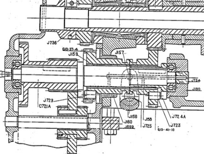
      The P&W has two single tooth clutches, one for forward feed / screwcutting and one for reverse. There is no provision for reversing spindle rotation.

      Found another picture and clipped the relevant parts showing both clutches. The actual gear train drive path for forward & reverse is "complicated".


      p&w clutches 2.jpg


      Its arguable that P&W designed the whole machine around exploiting the single tooth feed clutches. The main drive clutch lives in an oil tight box on the back of the machine with matching holes in headstock and box so the drive gear on the output side of the clutch can poke through to meet the input gear on the main speed selection box.

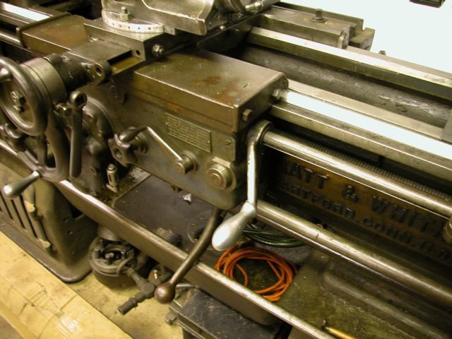
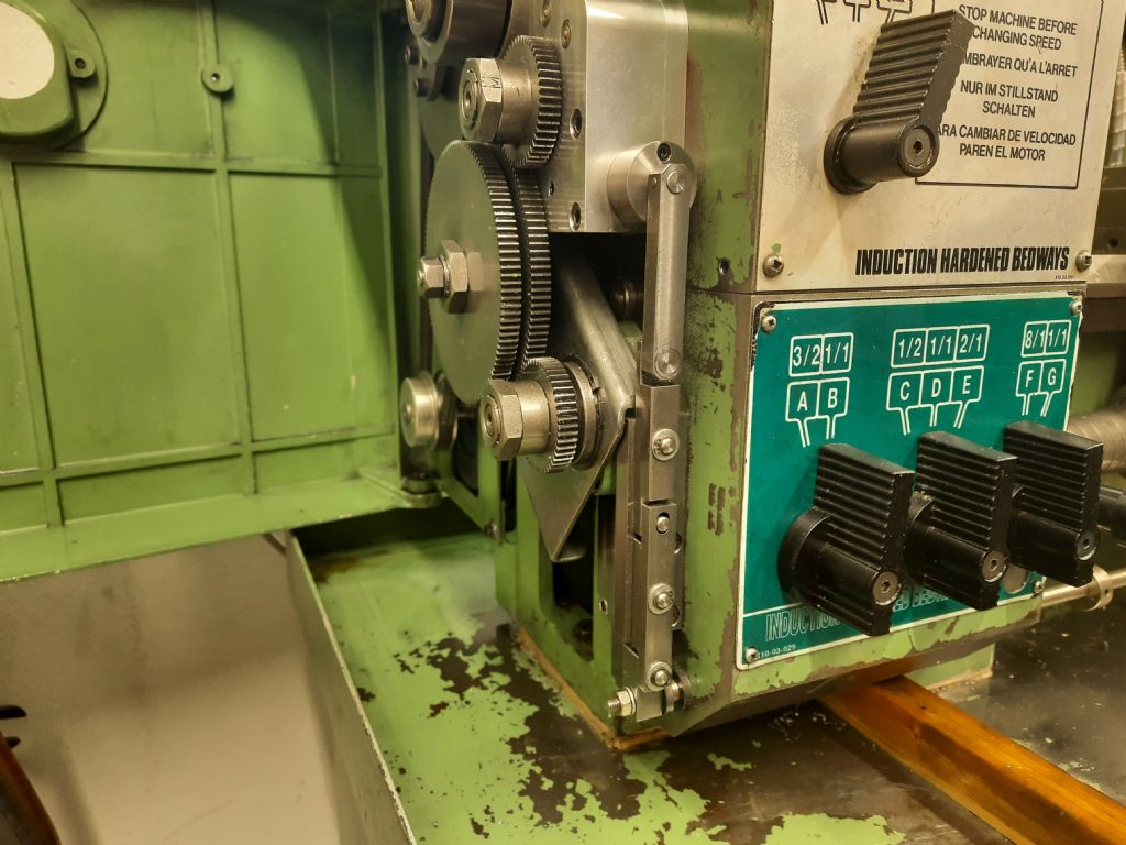
      Control via a lever on the saddle which rotates the stop rod. Push down for forward, pull up for reverse. Stop rod is 7/8" diameter with appropriately massive clamps.

      neutral.jpg


      Fine adjustment thimble on the left side of the saddle too. Its very convenient. Have to remember to stop the spindle with the main clutch above 300 rpm before using the single tooth clutches.

      Clive

      Edited By Clive Foster on 06/03/2021 14:04:21

      Advert
      #532483
      Tony Ray
      Participant
        @tonyray65007

        Thanks for the detailed explanation of the P&W which I don’t fully understand but I ‘m sure will prove useful to others and maybe myself in developing an M250 solution.

        #532488
        Tony Ray
        Participant
          @tonyray65007

          Ok I think I have the STS solution figured out, I had a light bulb moment last night so here goes:

          A 30T gear fitted with a drive dog is fixed to the output shaft from the lathe . Engaged with this gear is a 15T idler that is wider so that it engages with a second 15T idler which then drives a second 30T gear also fitted with a drive dog that is free to rotate on the final output shaft. The two dog gears face each other and interposed is a clutch plate that is slid either to the left or to the right to engage with either drive dog. The clutch plate is keyed to the final output shaft. When slid to the right the clutch plate and therefore the final output shaft is driven in the same direction of rotation as the lathe output shaft. When slid to the left it rotates in the opposite direction because the second dog gear is driven off the first dog gear via two idlers which reverse the rotation. Because the idlers have the same 15T tooth count and both dog gears 30T the final output shaf rotates athletic same speed as the lathe output shaft no matter which way the clutch is driven. Finally for the sak of completeness the clutch is actuated with manual via the knobbed lever that project towards the from of the lathe or by the trip mechanism which runs down to the trip bar.

          I think that it, this will help me figure out what my solution.

          #532516
          Clive Foster
          Participant
            @clivefoster55965

            Tony

            Sounds like that will work just fine.

            But the M250 has a feed reverse already so one bi-directional clutch will do the deed. The drive pin doesn't care which side of the dog it engages with.

            So it all becomes much simpler as only two gears are needed and everything can be concentric. Need to change the label on the headstock forward / reverse feed selector knob tho' as the output drive gear will now be running backwards.

            Anyway thanks to this discussion I've had my own light bulb moment as to how to do the job on my 1024. Also concentric and geared down with bi directional clutch but inside out and back to front with the input gear free running.

            Clive

            Edited By Clive Foster on 08/03/2021 10:25:13

            #532539
            Graham Meek
            Participant
              @grahammeek88282

              Hi Tony,

              Your solution will work fine and is exactly how Trevor and I worked out the STS set-up. The automatic trip mechanism for the stops can be a bit more tricky to fit, but the permutations here are endless. While the trips to the rear of the bedway are usually more compact as regards any lever lengths. Having them at the front abutting the apron will make it more convenient.

              Having the internal feed direction change within the headstock is fine for doing left hand threads, or when the banjo set-up has an additional stud in the train from what it normally does. Once set, this internal gearing cannot be altered, as this will up-set your synchronisation point in the dog-clutch, by a factor of how many teeth are involved in the internal reversing gear.

              Regards

              Gray,

              #532687
              Tony Ray
              Participant
                @tonyray65007

                Clive: I’m glad I was of help in a “But I didn’t do anything” kind of way.

                Thanks Gray & Clive for confirming my understanding of the STS solution, it is not yet my solution for the Harrison, and finally thanks also Gray for ansewingbwhat was going to be my next question regarding the use of the lathes existing fwd / rev knob.

                #532743
                Graham Meek
                Participant
                  @grahammeek88282

                  Hi Tony,

                  This may, or may not be possible, but the idea has just come to me. As regards the Banjo, provided there is sufficient depth within the cover, the Banjo could remain at its current position, but be outboard of the screwcutting clutch.

                  The gear clusters on the Banjo being mounted on the inside of the Banjo rather than the outside as they currently are. A Steel plate Banjo would not need to be as thick as a Cast Iron one.

                  I know this might be a bit fiddly when setting up a gear train, but the need to change the set-up is fairly infrequent in my experience.

                  Regards

                  Gray,

                  #532781
                  Clive Foster
                  Participant
                    @clivefoster55965

                    Tony, Graham

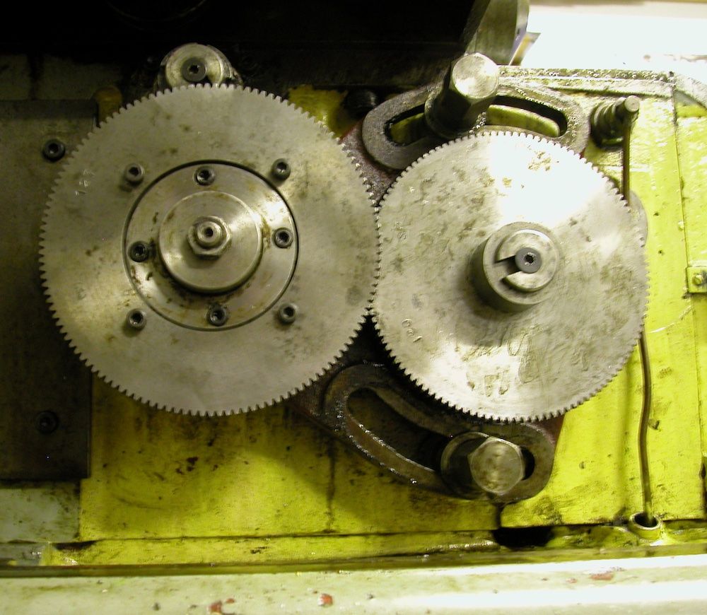
                    I'm struggling with similar space and output gear drive boss issues on the 1024. I have about 1" space behind the plane of the output gear and 1 1/2" in front of the plane of the banjo gear to play with. There is some upwards space above under a cover.

                    imperial conversion r.jpg

                    I have the 127 – 120 metric to imperial conversion gear pair permanently mounted so I only need to swop the spacer and gear order at the gearbox input to change. Headstock feed drive gear normally meshes with the 120 tooth transfer gear hiding behind the 127 gear in the picture.

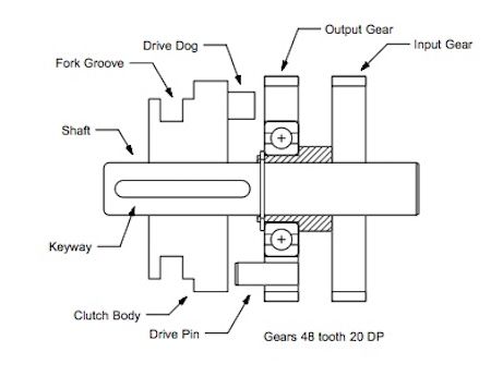
                    I propose to use a concentric system with bi-directional clutch tucked over to the left of the picture. Something like this :-

                    S&B single tooth clutch.jpg

                    Input gear and clutch body share a common splined or keyed shaft. Gear fixed, clutch sliding. The output gear is free running. The 127 and 120 tooth conversion gear pair will be reversed putting the 120 tooth gear on the outside to mesh with the clutch system output gear. An intermediate gear, not shown, will be needed to transfer drive from output gear to banjo gearing to avoid clashing with the 127 tooth gear which now lies on the same plane as the headstock feed drive gear.

                    Hopefully it will all sqeeze in.

                    Clive

                    #532815
                    Graham Meek
                    Participant
                      @grahammeek88282

                      maximat screwcutting clutch mk 2-cross section.jpg

                      This is the cross section through the Maximat Clutch, note the one Dog gear takes its drive directly from the wider output gear from the headstock' This gear also meshes with the idler gear shown below to reverse the direction to the other Dog gear. (Shown in mesh).

                      the parts that makes up the screwcutting clutch for the maximat.jpg

                      The above are the elements necessary to make the dog clutch work on the Maximat.

                      the dog clutch proper.jpg

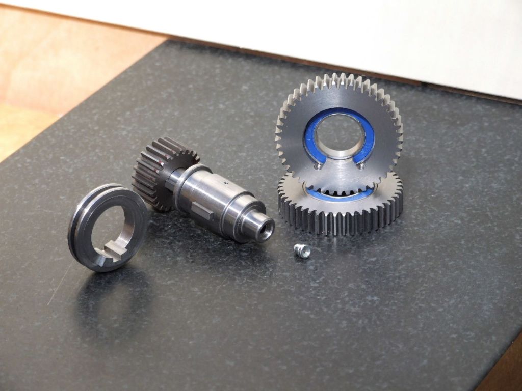
                      Above are the two Dog gears, the Double sided Dog clutch and the output gear on the Clutch shaft. Only the Dog clutch is keyed to the Clutch shaft. Drive to the output gear is only achieved by selecting a direction with the control lever.

                      clutch control lever.jpg

                      This connects to the stop rod which carries the stops.

                      trip rod attachment and stop.jpg

                      support for trip rod, tailstock end.jpg

                      These then are the elements required for a successful clutch.

                      Regards

                      Gray,

                      #532824
                      Tony Ray
                      Participant
                        @tonyray65007

                        Hi Clive, as you say you don’t have a lot of room to work with. The operation of you coaxial clutch is straightforward and I’m assuming that that’s a schematic as there looks like a lot of opportunities to make it more compact. Unlike you I need to change form metric to imperial quite regularly as I only have one machine. I would imagine you have the P&W for imperial and the S&B for metric?

                        #532826
                        Tony Ray
                        Participant
                          @tonyray65007

                          Hi Gray, I will keep the alternative banjo idea in mind but I’m going to try to develop the second shaft arrangement. Your comment re keeping the new output shaft on the same circle in relation to the input shaft he to screw cutting box was very helpful. I lie the idea of using an HTD belt to transfer motion to the new shaft but the shortest length seems to be 300mm so it might need a jockey wheel to fold it into the space required.

                          I think relocating the banjo is not going to be an issue and one I can manage.

                          Thanks for future explaining the your Emco version, what is the piurpose of the other gears that are in it ?

                          Regards

                          Tony

                          #532937
                          Graham Meek
                          Participant
                            @grahammeek88282

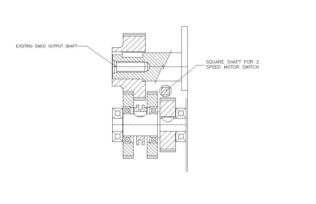
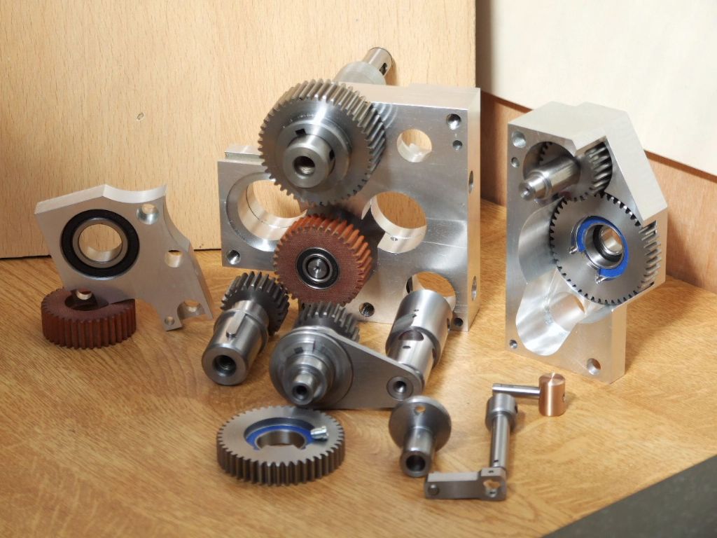
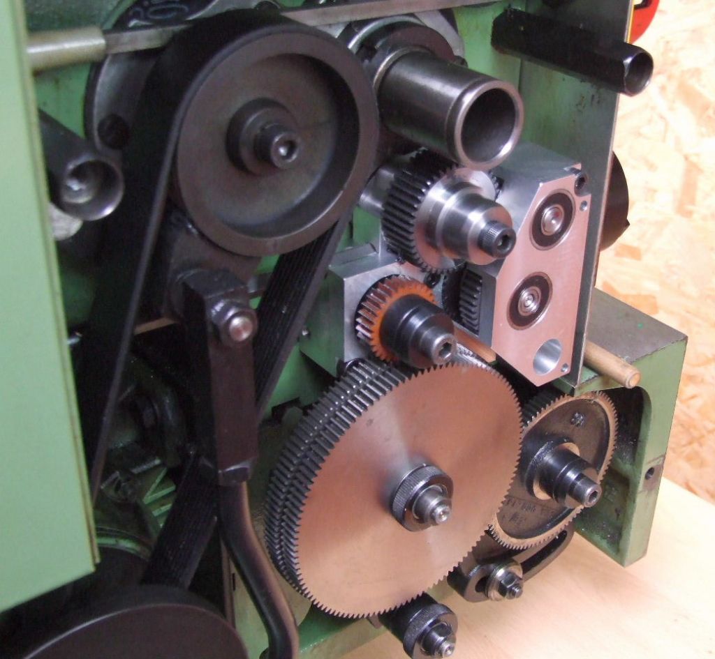
                            Above the two smaller cast iron gears and the Tufnol intermediary gear take the drive from the clutch output shaft to the new Banjo drive gear position.

                            As stated before the new Banjo drive gear position is on a common radius with the original Emco output shaft, taken from the screwcutting gearbox input shaft.

                            The photograph below shows the original shaft with the wide gear on and the new shaft at about 7.00 o'clock.

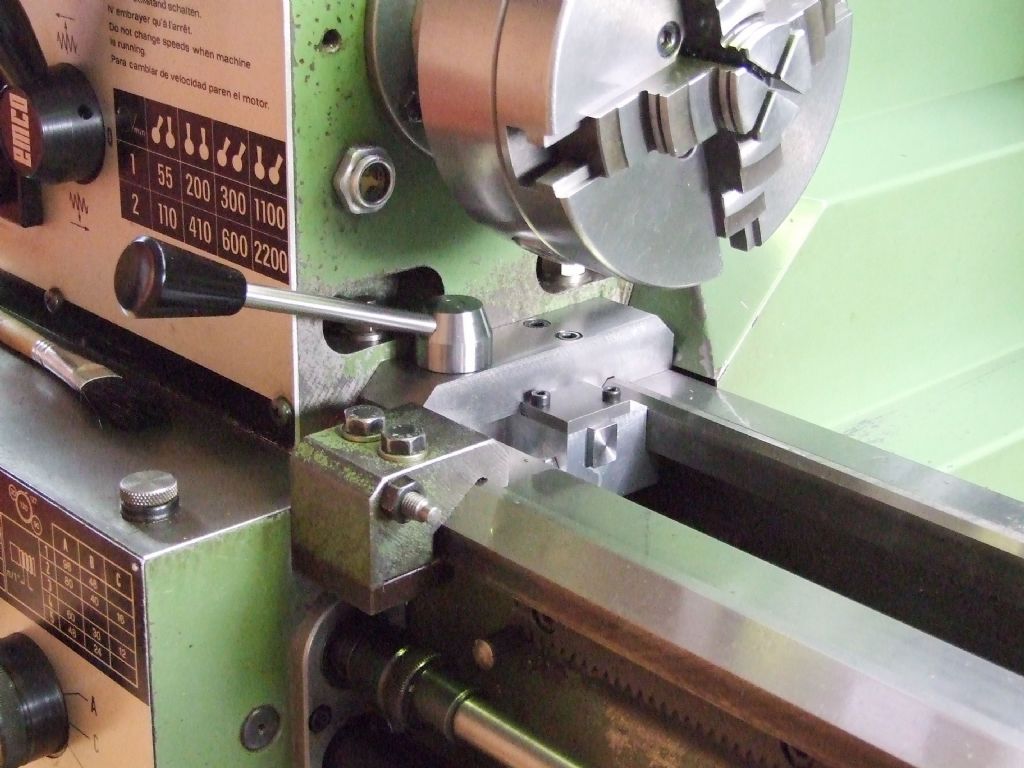
                            clutch fitted.jpg

                            All the operating mechanism is hidden from view and goes under the headstock to the lever at the front.

                            Regards

                            Gray,

                            #534398
                            Trevor Steele
                            Participant
                              @trevorsteele20547

                              Hi Everyone

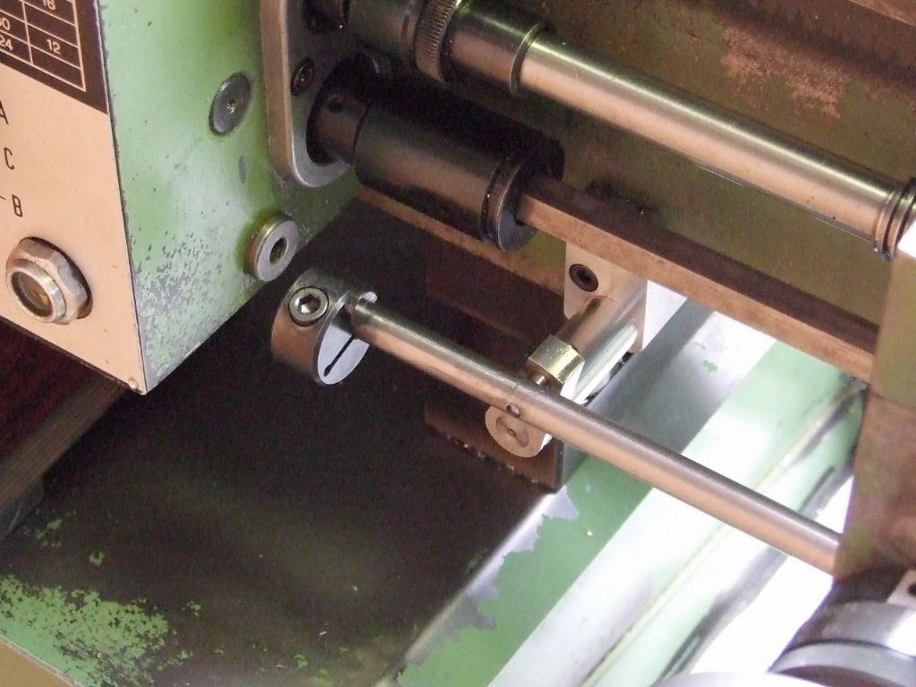
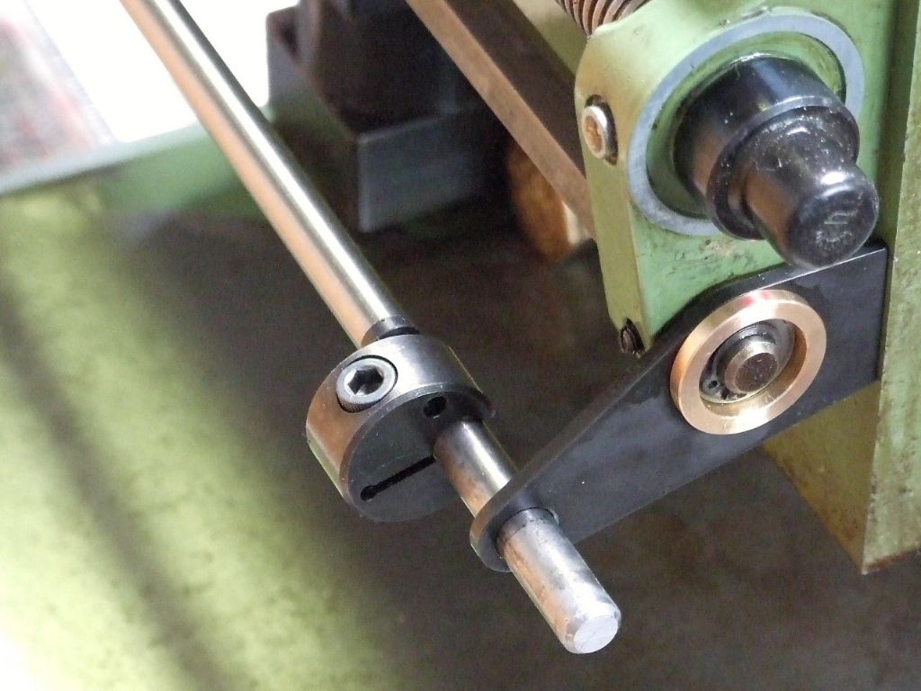
                              Just to update you on the tests I have been doing on the end stop accuracy issues. In my last correspondence with Gray, he had suggested using a double lever linkage between the operating rod and the shortened operating lever. This would be more rigid and still allow the greater sensitivity of using the short operating lever. I had previously considered a similar idea but dismissed it on the grounds of complexity.

                              Having decided it was with a try I have now built the linkage and tested it. It is a significant improvement over the previous versions, with the end stop position being much more repeatable. Those who had requested drawings have been sent updated versions of the new design. It will also be easy to change for the various versions of the X10 Boxfords which have differing swings, by simply altering the lever lengths.

                              A picture of the new linkage is shown below.

                              20210317_152654.jpg

                              #534413
                              Graham Meek
                              Participant
                                @grahammeek88282

                                Hi Trevor,

                                I had a feeling that this type of arrangement would give you a better result as regards repeatability. The other advantage is you can set your trip distance to a convenient dimension purely by juggling the lever lengths.

                                Thanks for trying out my suggestion.

                                Regards

                                Gray,

                                #534416
                                Trevor Steele
                                Participant
                                  @trevorsteele20547

                                  Hi Gray,

                                  A pleasure, your suggestion was spot on as always.

                                  Best regards

                                  Ttevor

                                  #534473
                                  Pete.
                                  Participant
                                    @pete-2

                                    Hi Trevor,

                                    I received your email, thank you very much for taking the time to update us with your achievements, impressive stuff.

                                    Thanks again, Pete

                                    #537959
                                    Don Pittman
                                    Participant
                                      @donpittman39809

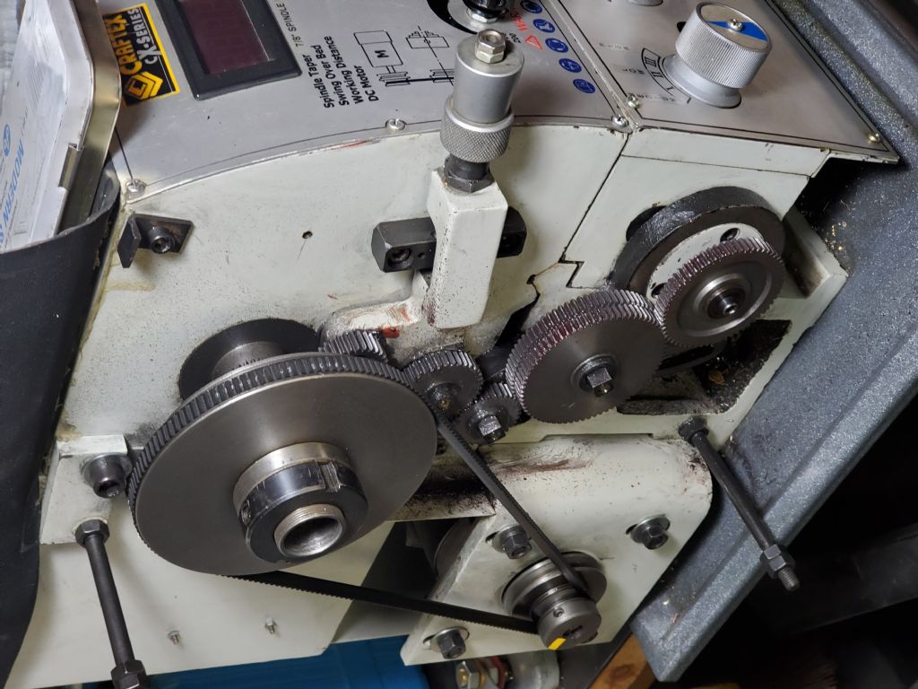
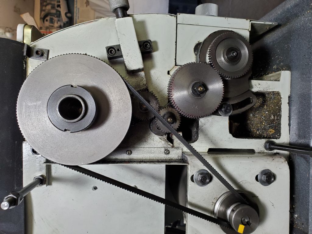
                                      I'm trying to understand how to adapt the Meek design to my Asian made 10×22 lathe. I've read many different adaptations but just seem to confuse myself more.

                                      Very very similar lathes to mine have had the clutch fitted to them successfully but my lathe has some differences and I'm not sure how to calculate the changes needed. The similar lathes that I have read about having the clutch adapted to them are the Grizzly and Warco lathes. My lathe is a Canadian "Craftex" 10×22 lathe with a bit different gear train in it.

                                      I'm hoping someone might be able to help me with what I need to figure out.

                                      I appreciate all the information and sharing you fine folks have done.

                                      Don

                                      #537965
                                      Tony Ray
                                      Participant
                                        @tonyray65007

                                        Hi Don,

                                        Please post some images of your lathe’s gear train and if you have any details of the clutch implementation on the similar lathes you mention those too so we can see where you are struggling.

                                        In case you need it: To post images you need to create an album to which you can upload them, from there you can then select them when you are writing you forum post.

                                        Tony

                                        #538012
                                        Graham Meek
                                        Participant
                                          @grahammeek88282
                                          Posted by Don Pittman on 04/04/2021 04:37:35:

                                          I'm trying to understand how to adapt the Meek design to my Asian made 10×22 lathe. I've read many different adaptations but just seem to confuse myself more.

                                          Very very similar lathes to mine have had the clutch fitted to them successfully but my lathe has some differences and I'm not sure how to calculate the changes needed. The similar lathes that I have read about having the clutch adapted to them are the Grizzly and Warco lathes. My lathe is a Canadian "Craftex" 10×22 lathe with a bit different gear train in it.

                                          I'm hoping someone might be able to help me with what I need to figure out.

                                          I appreciate all the information and sharing you fine folks have done.

                                          Don

                                          Hi Don,

                                          Some while back Jim Schroeder did a version for the Grizzly lathe which looks very much like your machine. There are a couple of Jim's videos out there and he also did a write up on his conversion in Home Shop Machinist. I think the articles appeared at the very end of 2014 or the beginning od 2015.

                                          There is another version which was for the older 918 lathe, but I am not familiar with this attachment as I have only seen one photograph of this. This is by a fellow MEW's author, who's name escapes me at the moment. I am pretty sure he lives in New Zealand and is an electrician, but that is all my grey matter will allow.

                                          Regards

                                          Gray,

                                          #538087
                                          Don Pittman
                                          Participant
                                            @donpittman39809

                                            Thank you for the guidance and information so far.

                                            I have read the Jim Schroeder article where he adapted the clutch to fit his Grizzly G0602 lathe. The G0602 lathe is very similar to my Craftex CX700 and I believe they are both built using the same castings/platform. I believe the Schroeder adaptation plan would be mostly correct for my lathe but……

                                            There are some differences between the lathes that would need to be addressed to make the Schroeder adaptation fit my lathe, but I do not have the mechanical mental ability and know how to grasp exactly how and what those changes would look like.

                                            My lathe came equipped from the factory with a reverse tumbler mechanism. Does this get superseded/eliminated with the clutch?

                                            My lathe uses module 1 gears as opposed to module 1.5 gears used in the Grizzly G0602. How and what do I need to figure out how to make changes for that difference?

                                            Here are a couple of pictures of my lathes gear train.

                                            20210404_104250.jpg20210404_104220.jpg

                                            Edited By Don Pittman on 04/04/2021 23:23:24

                                            Edited By JasonB on 05/04/2021 07:03:01

                                            #538140
                                            Graham Meek
                                            Participant
                                              @grahammeek88282

                                              Hi Don,

                                              The Tumbler Reverse Lever is redundant with a screw cutting clutch fitted.

                                              A lot of these machines have their heritage in the Emco Compact 8. This was adapted in the Far East to become the 918, which I am sure your lathe derivative is based on. I am also sure the photograph I saw of a screw cutting clutch fitted to a 918 will fit your lathe.

                                              I think the guys name is Brett Merkle? (I may have the spelling wrong, for which I apologise).

                                              He recently wrote an article in Model Engineers Workshop where he fitted a clutch to the main drive of this lathe. He is the man you really need to contact. Perhaps The Editor, Neil Wyatt would forward your email to him?

                                              I am sorry I cannot help any further than this.

                                              Regards

                                              Gray,

                                              #538286
                                              Don Pittman
                                              Participant
                                                @donpittman39809

                                                Gray,

                                                Thank you for your response sir. Just knowing that my reverse tumbler becomes redundant with the dog clutch mechanism gives me hope that I might be able to figure out Schroeders version and make it work with my lathe. I will look for contact with the gentleman you suggested.

                                                Thank you again for your direction and I wish you good health.

                                                Don

                                                #538332
                                                Graham Meek
                                                Participant
                                                  @grahammeek88282

                                                  Hi Don,

                                                  I have sent you a PM,

                                                  Regards

                                                  Gray,

                                                  #538335
                                                  BS Meacle
                                                  Participant
                                                    @bsmeacle

                                                    Hello Graham and Don

                                                    I have been a member of the forum for a while although not a practising member. It was actually the forum that got me into MEW as I was one of Neil's lost authors from an article I sent in many many years ago.

                                                    Gray, I am honoured you remembered my work and your confidence that my ideas may be able to help.

                                                    My attachment does not have quite the same refinements and finish as your work and other versions, but does work as designed, making screw cutting a pleasure.

                                                    My lathe being the older square style headstock also has no gearbox fitted. I have been curious for some time about fitting the clutch to the newer curved headstock style lathe c/w gearbox. A different design operating handle handle and trip mechanism would be needed. I have only seen a video of the Jim Schroeder Setup and would like to see more of his version.

                                                    I have added some Photos to an album if you wish to have a look. Please contact me if you want any more information or assistance, and I am always willing to learn from others too.

                                                    Regards,

                                                    Brett

                                                    #538375
                                                    Graham Meek
                                                    Participant
                                                      @grahammeek88282

                                                      Hello Brett,

                                                      First of all my apologies for getting your surname wrong. Memory recall for me these days is a problem.

                                                      It might come a surprise to you that I have long admired your work, especially the adaptations you have made to your lathe. George Thomas would be proud of you. Thanks also for the additional photographs.

                                                      Your design of screw cutting clutch I feel will also fit the Emco Compact 8, and would be far less work than my design, which to date has not been proven.

                                                      I also feel Don would benefit from your design, did you make any drawings?

                                                      Regards

                                                      Gray,

                                                    Viewing 25 posts - 51 through 75 (of 77 total)
                                                    • Please log in to reply to this topic. Registering is free and easy using the links on the menu at the top of this page.

                                                    Advert

                                                    Latest Replies

                                                    Home Forums Manual machine tools Topics

                                                    Viewing 25 topics - 1 through 25 (of 25 total)
                                                    Viewing 25 topics - 1 through 25 (of 25 total)

                                                    View full reply list.

                                                    Advert

                                                    Newsletter Sign-up