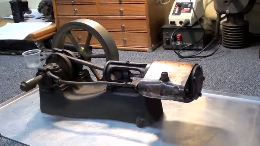
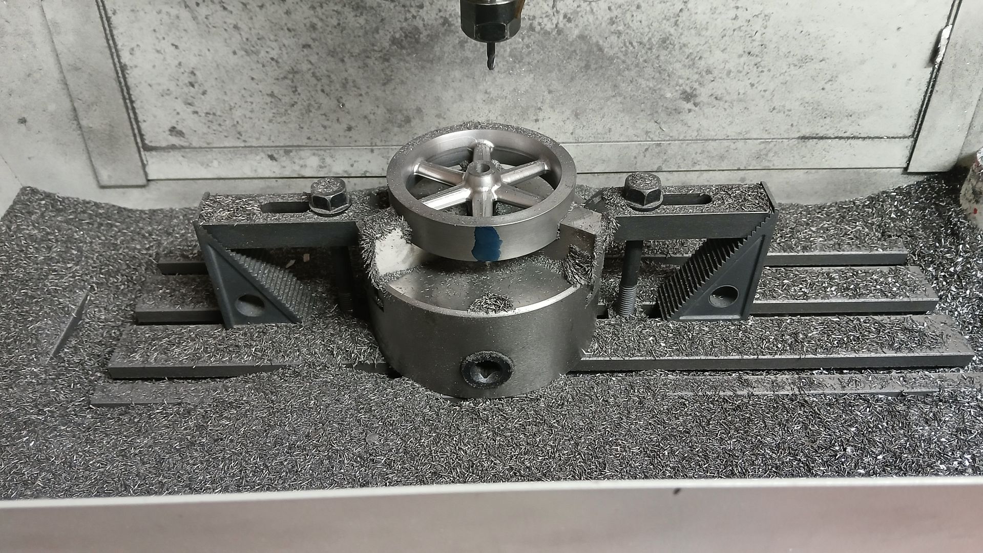
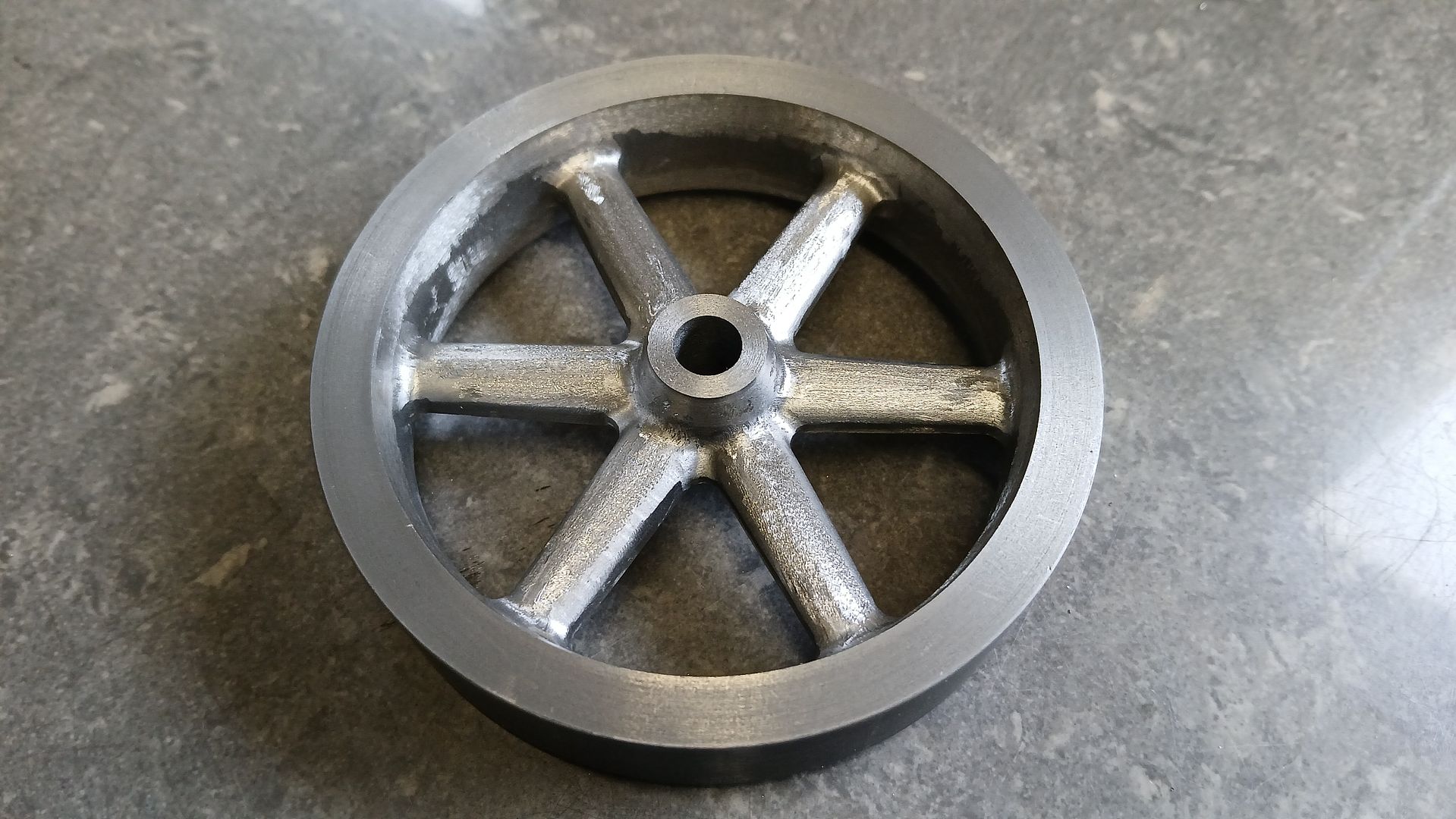
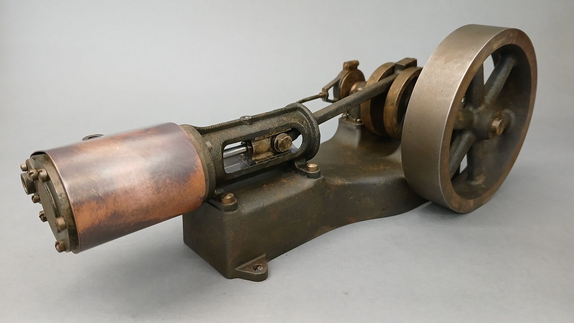
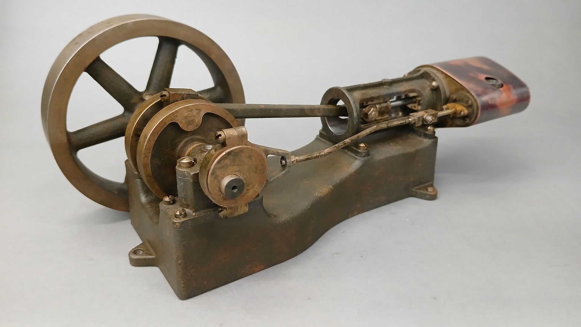
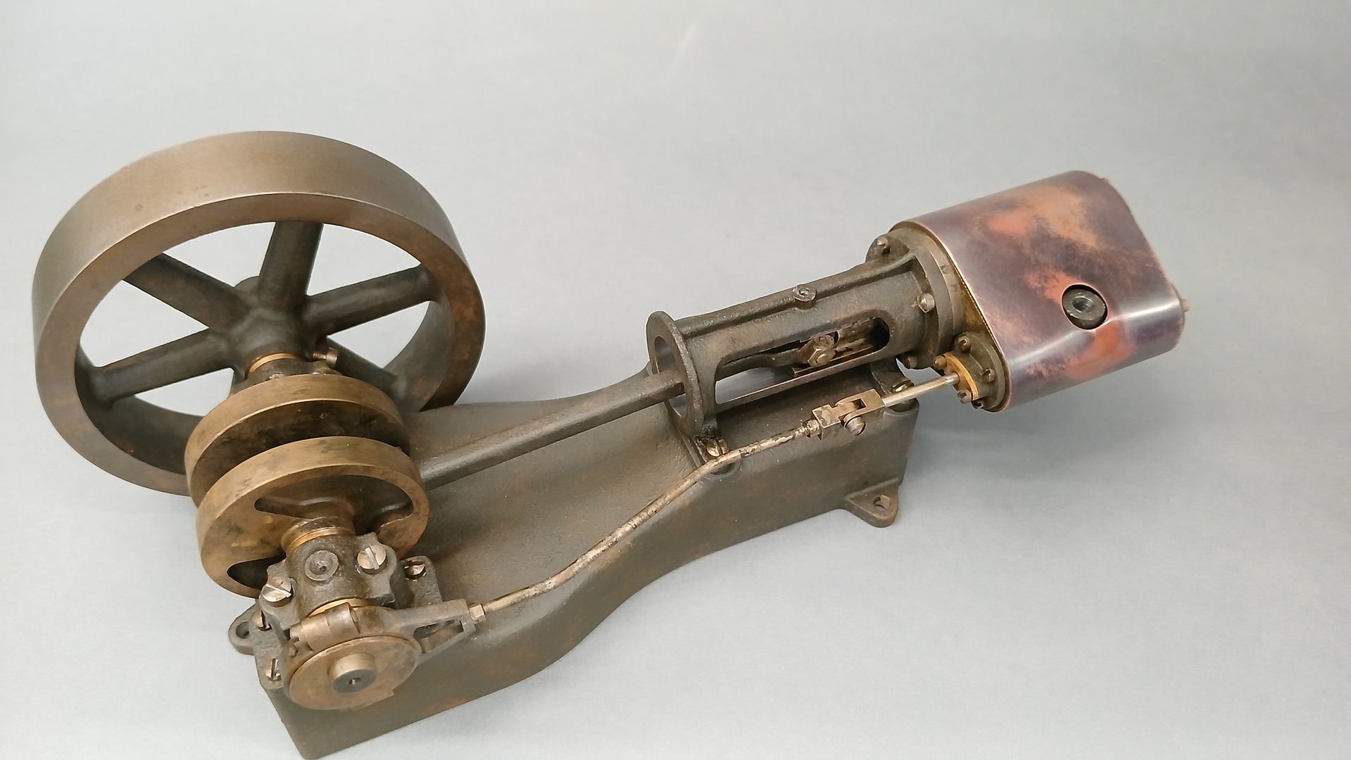
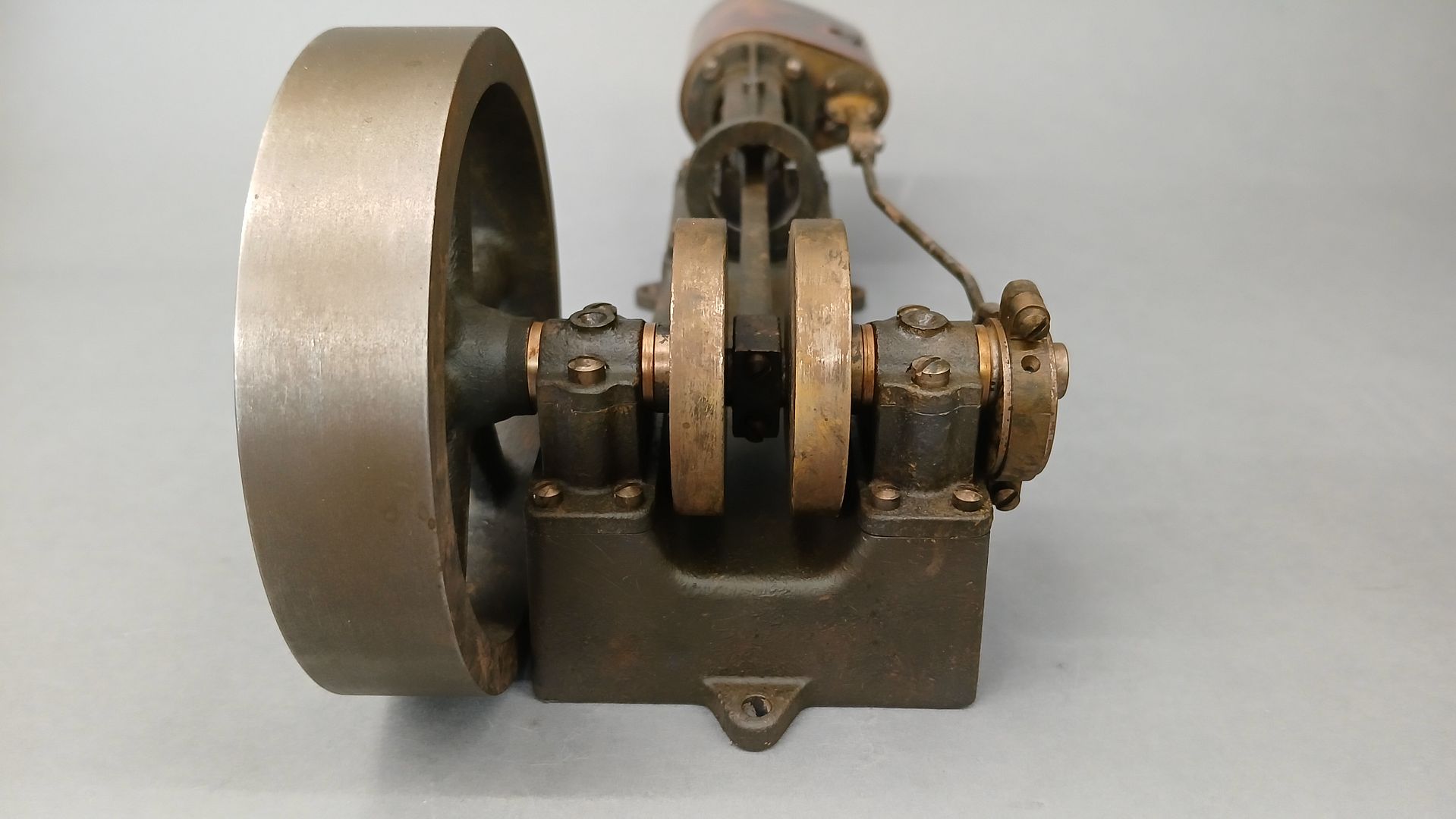
Half Scale 1/4HP A J Weed Engine
Half Scale 1/4HP A J Weed Engine
- This topic has 22 replies, 4 voices, and was last updated 12 May 2025 at 17:52 by
 Diogenes.
- Please log in to reply to this topic. Registering is free and easy using the links on the menu at the top of this page.
Latest Replies
-
- Topic
- Voices
- Last Post
-
-
Help please! Workshop clearance
Started by:
ksw
in: General Questions
- 2
-
25 June 2026 at 15:11
ksw
-
LINKS FOR WORKSHOP AND MODEL ENGINEERING STLs AND OTHER FILES
Started by:
Neil Wyatt
in: 3D Printers and 3D Printing
- 3
-
25 June 2026 at 14:34
DC31k
-
ML7 – Zeroing the Topslide?
1
2
Started by:
Dr_GMJN
in: Workshop Techniques
- 22
-
25 June 2026 at 14:33
ega
-
Rapidor 3XM
Started by:
homecat88
in: Introduce Yourself – New members start here!
- 3
-
25 June 2026 at 14:23
homecat88
-
How Good Are 3D Printers?
1
2
Started by:
Neil Wyatt
in: 3D Printers and 3D Printing
- 15
-
25 June 2026 at 11:22
Neil Wyatt
-
Hot radiators in summer
Started by:
Gary Wooding
in: The Tea Room
- 13
-
25 June 2026 at 11:17
Howard Lewis
-
3D Printing in the Home Workshop
Started by:
Colin Heseltine
in: 3D Printers and 3D Printing
- 7
-
25 June 2026 at 11:17
Neil Wyatt
-
Hot milk variations
Started by:
Gary Wooding
in: The Tea Room
- 12
-
25 June 2026 at 10:53
Nicholas Farr
-
Moving a Chester MF42Bb(removing milling tool)
Started by:
bowmandj1953
in: Introduce Yourself – New members start here!
- 3
-
25 June 2026 at 10:49
bowmandj1953
-
Letters and Parcels Box
Started by:
Michael Gilligan
in: The Tea Room
- 9
-
25 June 2026 at 10:15
noel shelley
-
24cc DIESEL ENGINE FROM SOLID
1
2
3
Started by:
dean clarke 2
in: I/C Engines
- 13
-
25 June 2026 at 06:21
dean clarke 2
-
Running 380V 3-phase motor on 230V 1-phase
1
2
Started by:
jimalm
in: Electronics in the Workshop
- 15
-
25 June 2026 at 00:54
Andrew Kett
-
Model Turbines
1
2
…
26
27
Started by:
Turbine Guy
in: Stationary engines
- 28
-
24 June 2026 at 21:02
Turbine Guy
-
digital microscope for poor eyesight
Started by:
bernard towers
in: Electronics in the Workshop
- 14
-
24 June 2026 at 19:40
Neil Wyatt
-
Testing Single Point Thread Fitment
Started by:
berwick
in: Beginners questions
- 13
-
24 June 2026 at 15:42
berwick
-
Emco Compact 5 milling table restoration
Started by:
rikt
in: Manual machine tools
- 5
-
24 June 2026 at 15:34
rikt
-
FARM BOY Ignition
Started by:
Speedy Builder5
in: I/C Engines
- 3
-
24 June 2026 at 15:17
Speedy Builder5
-
Gas Tap Valves. Vintage
1
2
3
Started by:
dee
in: Related Hobbies including Vehicle Restoration
- 19
-
23 June 2026 at 21:24
Nigel Graham 2
-
Taylor Hobson Pantograph Engraver Model D
1
2
Started by:
jaCK Hobson
in: Workshop Tools and Tooling
- 10
-
23 June 2026 at 21:05
Charles Jambon
-
Rapidor Manchester re-build
Started by:
homecat88
in: Introduce Yourself – New members start here!
- 3
-
23 June 2026 at 19:19
homecat88
-
Advice required
Started by:
janet.ho001
in: Introduce Yourself – New members start here!
- 4
-
23 June 2026 at 19:12
janet.ho001
-
Orbital – Not your Usual Oscillator!
1
2
Started by:
JasonB
in: Stationary engines
- 14
-
23 June 2026 at 19:11
JasonB
-
Clarkson Horizontal – Redefined in Metric
Started by:
JasonB
in: Stationary engines
- 8
-
23 June 2026 at 18:48
JasonB
-
Rob Roy Build
Started by:
Dalboy
in: Locomotives
- 4
-
22 June 2026 at 21:24
Dalboy
-
Help identifying a mystery thread
Started by:
Beardy Mike
in: Beginners questions
- 8
-
22 June 2026 at 19:04
Nicholas Farr
-
Help please! Workshop clearance
Latest Issue

Newsletter Sign-up
Latest Replies
- Help please! Workshop clearance
- LINKS FOR WORKSHOP AND MODEL ENGINEERING STLs AND OTHER FILES
- ML7 – Zeroing the Topslide?
- Rapidor 3XM
- How Good Are 3D Printers?
- Hot radiators in summer
- 3D Printing in the Home Workshop
- Hot milk variations
- Moving a Chester MF42Bb(removing milling tool)
- Letters and Parcels Box

