Hi,
Marvellous how your brain works in the bath!
Ok, back to first principles. Let's forget about reversing for now and just concentrate on getting the motor running. Now, both windings need to be powered for that to happen, except that one winding is straight across the mains supply and the other is via a capacitor. Secondly, we need to switch out of circuit the start capacitor when a suitable speed has been reached. Therefore I suggest the following:
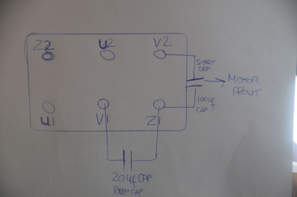
Connect U1 to Z1 and to either Live or Neutral, it doesn't matter which but see below. Now, one of the windings is permanently connected to the capacitors. Therefore that connection is NOT used. To start the motor both capacitors must be in circuit and then the one between Z1 and V2 disconnected. This is the start capacitor. Therefore connect the other mains lead to V1 and U2. The motor should now run. Note that there is no connection to V2.
Now, for motor running, we need a permanent power to one of the windings and reversible power to the other, but lets leave the reversible bit for the moment.
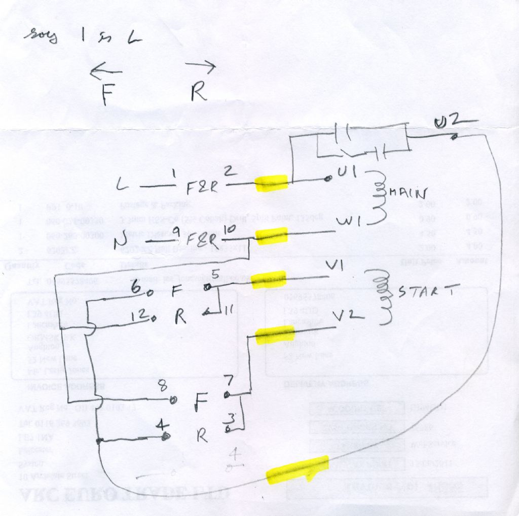
So, unplug the lathe from the mains, remove the DOL switch cover and see if you can operate the contactor by hand. If not, then see if you can identify the two leads running between the DOL unit and the FWD-Off-REV switch. If possible use the contactor method as this will prove the circuit right the way through. Connect your meter between the Live pin on the plug, operate the switch to Fwd, manually operate the contactor and look with the other meter lead on the connections to the motor, not the actual motor itself, one of the U1,U2,V1,V2 wires. You should, I think find two that are connected through. Move the switch to REV and one of the leads will become disconnected. The remaining lead will be your permanent Live lead. Repeat for the Neutral connection.
Now having identified the permanent Live and Neutral wires, you can connect to U1/Z1 and U2/V1 on the motor which should now run, unidirectionally only, but under control of the Fwd-Off-Rev switch. My suggestion based on the diagram in the article I suggested, would be to connect Neutral to V1/U2 and Live to Z1/U1. But if you do this, remember that the two unused wires will also be either live and neutral, or neutral and live. Please take care to make them safe.
Now to sort out the reversing. This can only be done by means of the U1-U2 winding, and if you only have four wires to the motor, then the two remaining wires are the ones to use. So remove the U1-Z1 and U2-V1 links leaving the two permanent power connections in situ on Z1(Live) and V1 (neutral). Now connect the two remaining wires to U1 and U2 and the motor should run and be reversible. If you have five wires, then I need to think again.
If the moter does run the wrong way, then either reverse the U1& U2 connections, or the Z1 and V1 connections.
Looking at the diagram in the reference I gave, it shows the capacitors connected to neutral. Therefore I would suggest that V1 should be neutral and Z1 Live.
Regards, and Goodnight,
Peter
Edited By Peter G. Shaw on 04/02/2014 23:21:49
Les Jones 1.


