How to stay in control of mill depth of cut? (My mill has no fine quill feed)

Advert

How to stay in control of mill depth of cut? (My mill has no fine quill feed)

Home Forums General Questions How to stay in control of mill depth of cut? (My mill has no fine quill feed)

Viewing 25 posts - 1 through 25 (of 46 total)
  • Author
    Posts
  • #22514
    Ian P
    Participant
      @ianp

      Emco Mentor FB1

      Advert
      #114216
      Ian P
      Participant
        @ianp

        On this machine model of machine the quill has the usual rack and pinion with crude calibrations, also with the quill in the retracted position it is totally enveloped by the head casting so there is no (straightforward) way of adding a readout scale.

        Even with scale fitted (or a dial indicator) it is not easy to make small vertical movements or adjustments to the depth of cut.

        At the moment I use the Z axis leadscrew (1.5mm pitch with 0,1mm increments) but I find that due to 'sticktion', the weight of the head and leadscrew backlash etc, the whole process is very hit and miss.

        I would like to be able to adjust the depth of cut in 0.02mm (or better) increments but at the moment the very best I can expect is to get within 0.1mm.

        Any suggestions appreciated.

        Ian

        Am I being unreasonable

        #114220
        Jeff Dayman
        Participant
          @jeffdayman43397

          You could add a worm wheel to the pinion axle and make a worm on a shaft with a crank for fine feed. This setup works well on my Taiwan-made mill. There is a cone clutch type device to disengage the worm from the shaft if the pinion and rack are to be used for drilling.

          Depending on the model of your machine there may be other models from same manufacturer with a setup as decribed above. If so, maybe you could buy the fine feed device as a spare part from the local dealer and adapt it to your machine.

          As to DRO, I added the Z axis readout scale to my mill by making adapter brackets to run parallel to the spindle but outside the head casting. Holes were drilled and tapped into the depth guide bracket at the bottom of the spindle to attach the lower moving end. If there is no such bracket on your mill you could easily make one from a piece of plate spilt in two with a hole in the centre closely fitting the spindle, and with two clamping screws either side of the hole. (if there is room for these arrangements in your mill.)

          Photos or at least the make and model of your mill would help us make better suggestions.

          JD

          #114221
          JasonB
          Moderator
            @jasonb

            Can you tell us what the mill is as it may help what to suggest. You could possible add a wheel to the quill spindle with a matching worm to drive it fitted with a callibrated handwheel which is what the Emco heads use

            My X3 has no fine quill feed I just use the Z axis to raise or lower the head thats 0.050" per turn so only a fraction finer than your 1.5mm. Had no problem before I fitted DRO and definately no problem now.

            J

            #114222
            Ian P
            Participant
              @ianp

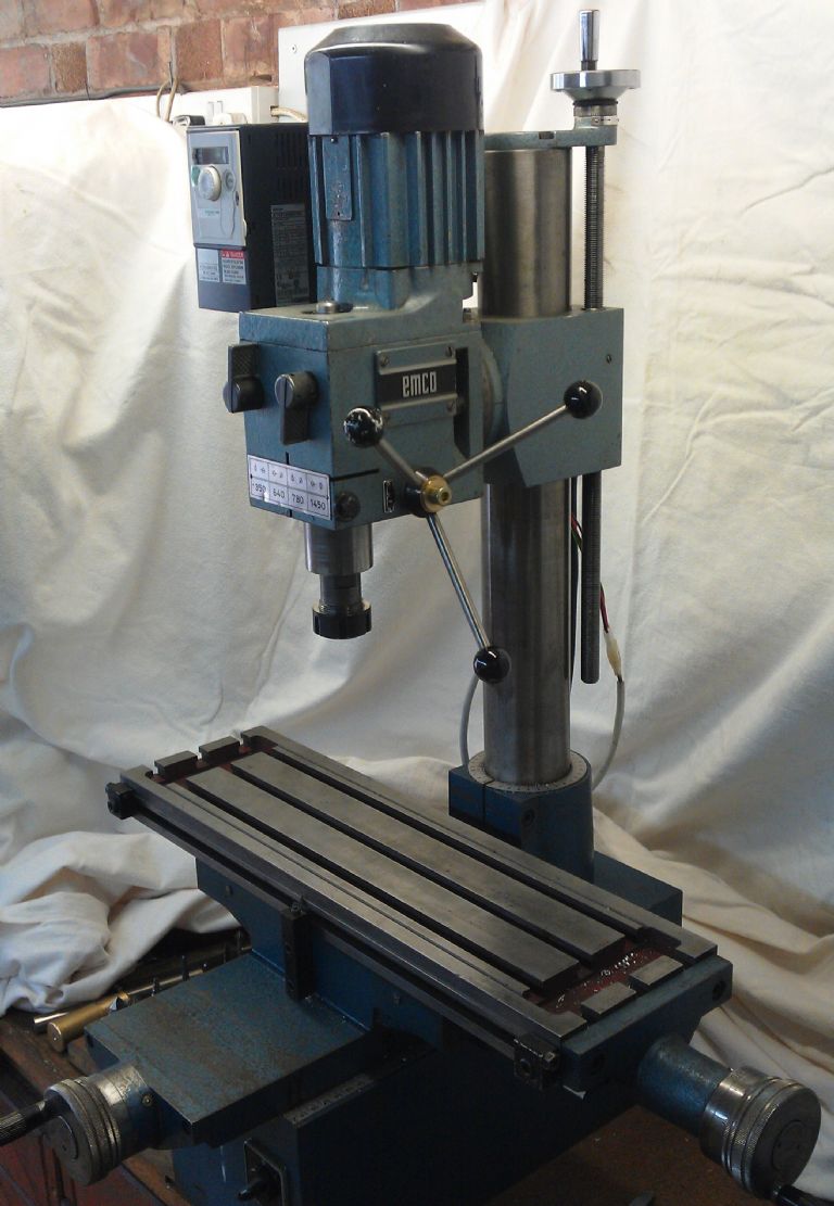
              The mill is an Emco 'Mentor' with a 4 speed geared head (FB1 I think).

              This picture shows the quill fully extended, when withdrawn it retracts completely into the head casting so I would have to lose some travel if I fitted a clamp ring etc (I have not ruled it out though)

              Ian

              emco mill-1.jpg.

              #114224
              Dunc
              Participant
                @dunc

                Found this one by googling "mill fine downfeed"

                **LINK**

                Acc to posts on HMEM (Home Model Engine Machinist) this group has a construction project on its site. I am not a member (don't own the machine myself).

                **LINK**

                Further posts on HMEM recommend a Google search for "Big Red Drill/Mill"

                I have a construction project/detail drawings (5 pages) as a pdf (~230 KB). No clue where I obtained it (or why I bothered to d/l it) but I will gladly attach to an email or (?) otherwise for forwarding. Looks very simple to build.


                Edit: Did not realize your make/model when I composed my reply. The "Big Red" reference is nothing like your machine. The pdf I have while shown on – I think – a similar machine looks as though the idea could be adapted.

                Edited By Dunc on 11/03/2013 21:23:45

                Edited By Katy Purvis on 12/03/2013 16:24:10

                #114225
                Ian P
                Participant
                  @ianp

                  One thing I have considered is mounting a small ballrace on top exposed end of the spindle and using to isolate the rotary movement, then coupling it to a dial indicator or linear scale.

                  It would only be worth doing if I added some form of fine feed like a worm and pinion, I would need a means of disengaging too.

                  I just wondered what other people do with quill-less mills? adjusting height with the leadscrew is fine if the mill head weight and freedom of movement always overcome the cutter load etc. I have the head to column fit fairly tight to minimise play but the head movement now sometimes leads, sometimes lags the leadscrew and nut.

                  Ian

                  PS, getting images on to this website is possible (obviously) but it does involve jumping through hoops!

                  #114232
                  Versaboss
                  Participant
                    @versaboss

                    ian, I see on your other photos that you added digital scales to a (this?) mill. So do it as I did on my Emco mill (I have the newer model, but think there is no difference in these parts:

                    – make an adaptor plate above the bracket which holds the z handwheel. It can be fastened with the same (or maybe a bit longer) 4 screws.

                    – make an adaptor plate and screw it to the side of the big square lump on which the head hangs.

                    – now mount a Chinese scale between these adaptor plates.

                    Just thinking about what I really did: the scale is free hanging (fixed on the top plate. only) The reading head is fixed on the lower adaptor. As usual the adaprors need some means to adjust the free running of the whole system, but in my case it works without troubles.

                    What wonders me a bit is that you have such a crude scale on Z. I did not work with my Emco since a long time (having other machines), but I can't remember that setting the vertical position is so coarse. I would not using the quill for setting depth; that's much too complicated to achieve any precision.

                    Greetings, Hansrudolf

                    Edited By Versaboss on 11/03/2013 22:29:34

                    #114236
                    Nobby
                    Participant
                      @nobby

                      Hi Ian
                      Why not fit one of these
                      Nobby

                      no drawbar

                      #114238
                      Andyf
                      Participant
                        @andyf

                        A digital readout would be good, but ff you don't fancy fitting one you could replace the existing dial with one of much bigger diameter. A 100mm dial would take 150 marks, each representing 0.01mm, and the marks would be just over 2mm apart. With a bit of ingenuity, an O-ring under a bit of compression could be incorporated 'twixt dial and shaft to make the dial zero-able.

                        Andy

                        #114241
                        Ady1
                        Participant
                          @ady1

                          At the moment I use the Z axis leadscrew (1.5mm pitch with 0,1mm increments) but I find that due to 'sticktion', the weight of the head and leadscrew backlash etc, the whole process is very hit and miss

                          —-

                          It's no different with an old cross slide, backlash etc can be a real pain on some machines

                          A DRO fixes all these issues, it really is a one shot fix

                          #114243
                          JasonB
                          Moderator
                            @jasonb

                            Try contacting Graham Meek he has done several mods to his FB2 and one may well be a fine feed. From his work he does not seem to have any problems with a similar mill.

                            As Jeff and I said Emco make a fine feed accessory for the smaller wills and may well do one for one like yours even if it needs a bit of adapting for the older model.

                            J

                            #114248
                            Jo
                            Participant
                              @jo

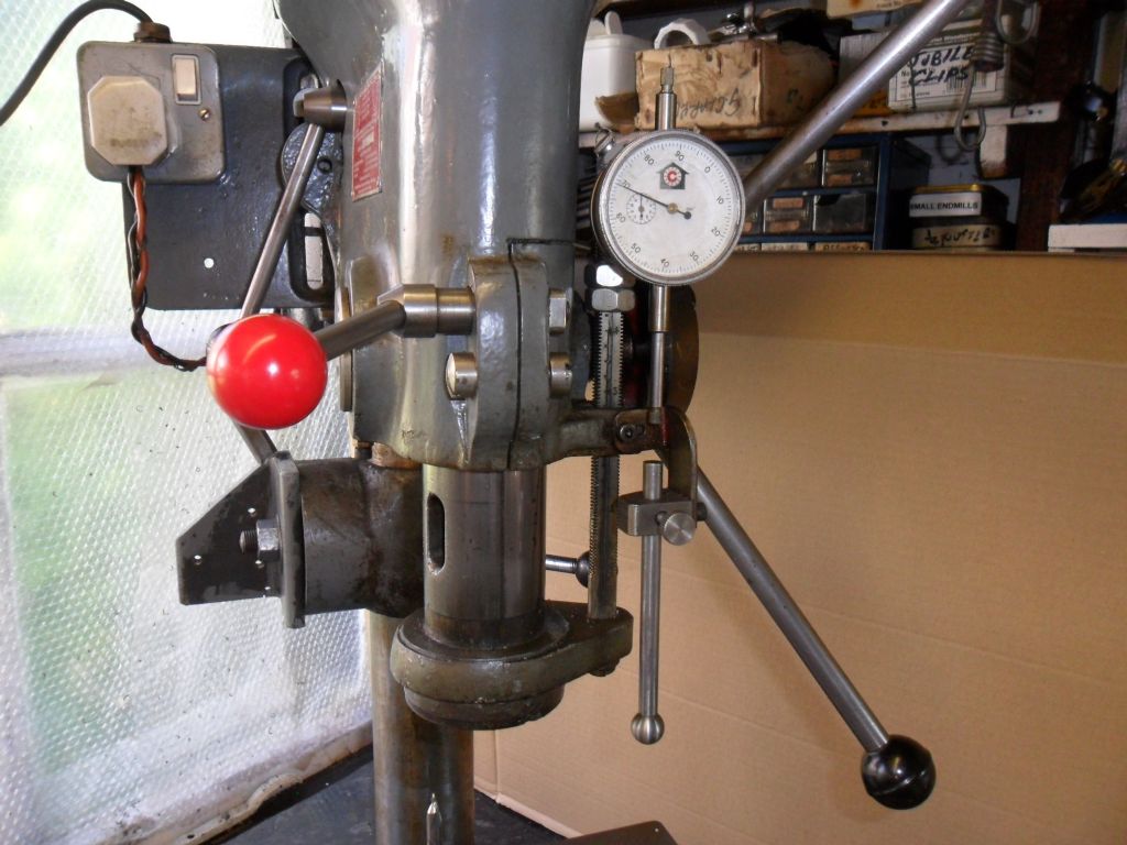
                              Ian my Prazimat mill is similar to your machine and I fitted a dia gauge on the top of the quill: Nothing exciting just drilled a hole in the top cover clamped the dial gauge with a grub screw and then added a little brass bush for when I was not using a draw bar:  I would have posted pictures of it but this forum software does not accept standard image codes for some reason.

                              I have put together a simple design and have all the parts to for a fine quill feed but have not yet got around to making it.

                              I also have a DRO on the Z axis and thanks Gray, will be taking your advice and giving it a good oiling as yes mine also sufferes from sticking.

                              Jo


                              Edited By Jo on 12/03/2013 10:22:39

                              Edited By Jo on 12/03/2013 10:25:48

                              #114277
                              Ian P
                              Participant
                                @ianp

                                Thank you gentlemen for all the suggestions.
                                Hansrudolf
                                In the past I kept trying to work out how to add a scale to the quill and totally missed the idea of putting on the head to column movement so thanks for suggesting it. I have a few Aldi calipers and I might use one of those as a temporary measure (pun!) with a simple sliding clamp so I can position it to cover the range as required. I got used to reading the caliper digits at right angles when I used themon the X and Y of an X1 mill.
                                I am not keen on using an index wheel on the pinion shaft, at best its only a guide and the pinion shaft on my mill is quite a loose fit in its bore so even the backlash is unpredictable.
                                Nobby
                                I have used a long travel dial indicator for that very purpose in the past, but on the Emco the bottom of the quill is not accessable in the up position (in fact the whole body of the quill is contained within the head casting).
                                Andy
                                Too much play in the rack and pinion and the pinion fit in its bore rule out going to the trouble of making a larger dial.
                                Ady
                                A lathe slide tends to stay where it is due to slide friction (unless the cutting force pushes it back). One can always counter the backlash by backing off and always aproaching in the same direction. Thats much harder to do when the weight of the mill head does not allways overcome the movement friction.
                                Gray
                                The Z axis marks are at 0.02mm increments which is fine. If I could ensure the head was always 'hanging' on the leadscrew threads than I would be more then satified. I adjusted the head/column fit off the machine until I was happy with it but once all reassembled I found I needed to tighten it up slightly to get a good vibration free finish.
                                Jo
                                Now that does look interesting! how does the tip of the plunger cope with the revolving spindle?
                                Ian
                                #114280
                                David Littlewood
                                Participant
                                  @davidlittlewood51847

                                  Ian,

                                  For real precision setting there is nothing which matches a DRO. That gives an absolute – and very precise – indication of the head position. It's a little trikier fitting one on the Z-axis, but it just needs a bit of imagination and some alloy brackets. Here is the one on my FB2:

                                  The Machine-DRO kit that I bought came with a generous supply of alloy bits to make brackets.

                                  The stick-slip issue still occurs, but at least you know that whatever the display says is accurate, you just have to learn to manage it (or cure it – must try some of the suggestions above!).

                                  David

                                  Edited By David Littlewood on 12/03/2013 14:51:43

                                  #114281
                                  Jo
                                  Participant
                                    @jo

                                    Ian, being that it is dead in the centre of the spindle and the dial guage has a hardened ball centre working against the piece of brass, no problem at all.

                                    Jo

                                    #114289
                                    Ian P
                                    Participant
                                      @ianp
                                      Posted by Jo on 12/03/2013 14:50:45:

                                      Ian, being that it is dead in the centre of the spindle and the dial guage has a hardened ball centre working against the piece of brass, no problem at all.

                                      Jo

                                      I did see your picture because its URL was in the notification email. However, if you do want to put images in the forum threads its easiest to first put them in a forum album, then link to that.

                                      I think I will use the same technique as you have on your mill but using a miniature ballrace assembly (foraged out of a hard disk drive). Having the scale or indicator tip referencing on the actual cutter spindle seems an intrinsically correct method.

                                      Ian

                                      #114293
                                      David Littlewood
                                      Participant
                                        @davidlittlewood51847
                                        Posted by Graham Meek on 12/03/2013 14:55:09:

                                        The only problem with the DRO set up as it is shown , is that the head can no longer be rotated via the column base clamp, this severly restricts the versatility of the machine.

                                        Gray,

                                        In the time I have had the FB2 (almost 30 years) I have never needed to swivel the column. Not even once. If I ever did, for some exceptional purpose, it would only take a few minutes to remove the Z axis scale. On the other hand, the Z-axis scale is used about half the time I'm using the machine (i.e. almost always for milling, hardly ever when drilling). Seems a fairly clear winner to me, but YMMV.

                                        David

                                        #114298
                                        Jo
                                        Participant
                                          @jo

                                          Ian: in light of the copyright clause on this forum I will not be using a forum album to host any of my photographs. If anyone wants to see the modification then it is available to all on this page: **LINK**

                                          Jo

                                          #114300
                                          NJH
                                          Participant
                                            @njh

                                            Jo

                                            Could you please point me to the copyright clause you cite.

                                            Regards

                                            Norman

                                            #114301
                                            Jo
                                            Participant
                                              @jo

                                              3. CONTENT SUBMITTED TO THE WEBSITE

                                              You acknowledge that MyTimeMedia does not always monitor Content (as defined below) submitted by users, but that MyTimeMedia shall have the right (but not the obligation) in its sole discretion to refuse or remove any Content that is available via the Website. Without limiting the foregoing, MyTimeMedia shall have the right to remove any Content that violates the Terms and Conditions of Use or is in any other way inappropriate or objectionable. You agree that you must evaluate, and bear all risks associated with the use of any Content, including any reliance on the accuracy, completeness, or usefulness of such Content.You may not submit third party proprietory information to MyTimeMedia without first obtaining permission from the owner. Any Content provided by you by, for example, posting messages to bulletin boards or chat forums, uploading files, inputting data, or engaging in any other form of communication through this Website, although owned by you, is subject to a royalty-free, perpetual, non-exclusive, unrestricted, world-wide licence allowing MyTimeMedia to use, distribute, copy, sub-license, adapt, transmit, publicly perform or display any such content. You agree to irrevocably and unconditionally waive on your behalf in perpetuity in respect of such Content the benefit of any provision of law known as moral rights of authors or any similar law in any country.

                                              Jo

                                              #114303
                                              NJH
                                              Participant
                                                @njh

                                                Thanks Jo

                                                N

                                                #114317
                                                David Littlewood
                                                Participant
                                                  @davidlittlewood51847

                                                  Graham,

                                                  Yes, I realise I could have fixed it to the column – the only reason I did not do this is that I didn't think of it at the time! As far as the length is concerned, once I was fixing it to the base then I needed the backing and cover, and the marginal cost of increasing the scale length is quite small.

                                                  I haven't quite worked out how rotating the column would allow you to do a longer machining run without resetting; surely that is governed by the table travel. I could still tilt the head to use as a horizontal borer without rotating the column – not that I ever have. Perhaps I've just not been as adventurous as you have been!

                                                  David

                                                  #114335
                                                  JasonB
                                                  Moderator
                                                    @jasonb

                                                    Gray you need to bear in mind that what looks a 500mm long scale will only have a usable length of about 350mm as the head does not travel all the way to the.

                                                    So I would say David has 350mm of reading length. If the scale were mounted on a clamp around the column then the head could not easily travel to the bottom of the column.

                                                    The scales are sold by their readable length not their overall length so thats  more than likely a 370mm scale with and overall length of around 21"

                                                    Edited By JasonB on 13/03/2013 10:30:28

                                                    #114581
                                                    JC Uknz 1
                                                    Participant
                                                      @jcuknz1

                                                      Just getting to know my new Sieg HM-10, yet to apply power to it, but it struck me that the adjustable lock on the dovetailed vertical pillar/slide could be used as a stopper once you had determined how much you wanted to take off? The DROs I read about above sound great

                                                      I do havea problem that while I have read and understood the dog-clutch mechanism for c hanging from ordinary to fine feed the indicator wheel for fine feed is not locked in the way I have experienced with other mills I have used. The supplier is at the other end of the country so I probably need to sort it myself, or learn how to do it properly …. suggestions most appreciated

                                                    Viewing 25 posts - 1 through 25 (of 46 total)
                                                    • Please log in to reply to this topic. Registering is free and easy using the links on the menu at the top of this page.

                                                    Advert

                                                    Latest Replies

                                                    Home Forums General Questions Topics

                                                    Viewing 25 topics - 1 through 25 (of 25 total)
                                                    Viewing 25 topics - 1 through 25 (of 25 total)

                                                    View full reply list.

                                                    Advert

                                                    Newsletter Sign-up