Unimat 3 Mill head Modulus

Advert

Unimat 3 Mill head Modulus

Home Forums Manual machine tools Unimat 3 Mill head Modulus

Viewing 16 posts - 1 through 16 (of 16 total)
  • Author
    Posts
  • #334848
    Pete Savage
    Participant
      @petesavage40461

      Hi guys, I’ve just been fiddling with a quite well worn unimat 3 lathe I recently bought, and in trying to sort a few things out, I found something rather interesting/ peculiar about the rack and pinion Z axis.

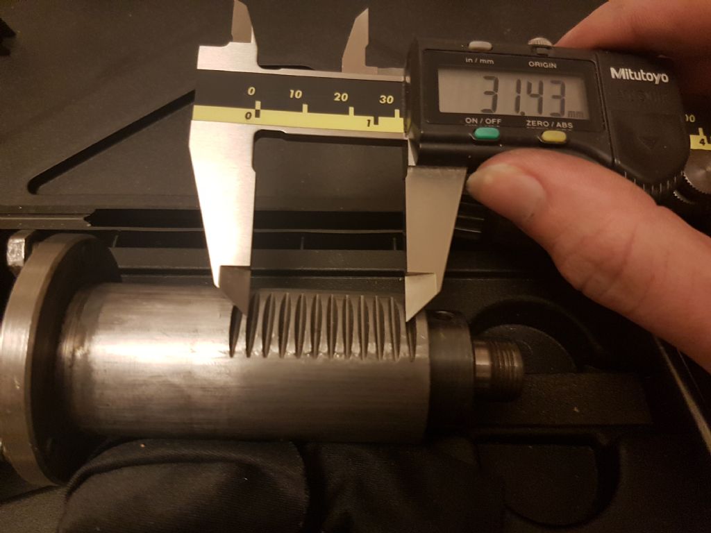
      The rack on the bearing carriage has a pitch of 3.14mm, which is a module of 1 (pi*mod) which I measured over 10 points and divided for better accuracy.

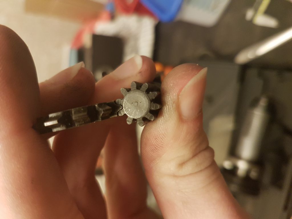
      Now when I look at the handle (which I am 99% certain is the original) and offer up gear cutters to it, the closest fit is a 0.9 modulus cutter.

      When the pinion is placed in the rack outside of the housing and rolled, it does not seem to move smoothly all the way.

      This seems like quite an oversight by emco unless it is for a reason?

      The reason I am going through it with a fine toothed comb is that I am looking to make a stepper motor attachment for it and the play that it has at the moment is not good enough.

      I will try and add some pictures when I work it out.

      I look forward to the discussion!

      Pete

      Advert
      #13112
      Pete Savage
      Participant
        @petesavage40461
        #334849
        Pete Savage
        Participant
          @petesavage40461

          20180102_003549.jpg

          Here is the bearing carrier with the Mod 1 rack

          20180102_003720.jpg

          This is the 0.9 cutter, and it may not look too conclusive from the image but the involute curves match pretty closely.

          20180102_003812.jpg

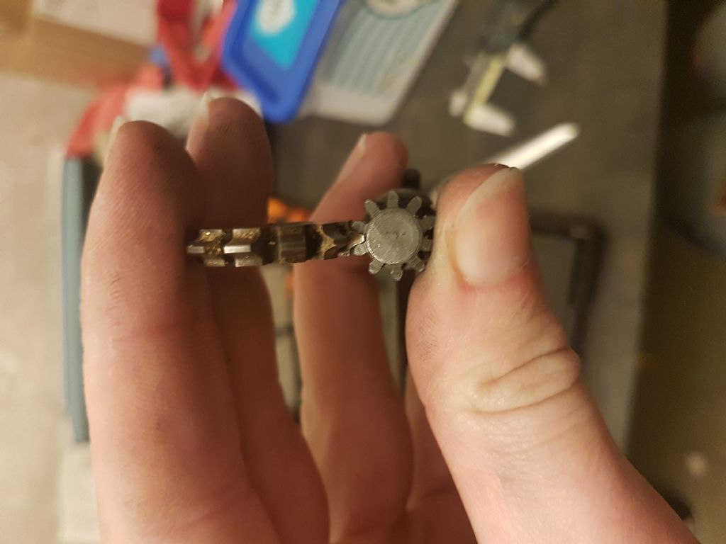
          None of the involute curves come anywhere close to touching on this gear cutter, yet the gear does not look excessively worn.

          #334850
          mahgnia
          Participant
            @mahgnia

            Pete,

            What's the OD of the pinion?

            Should be 12mm if MOD1.

            Andrew

            #334853
            JasonB
            Moderator
              @jasonb

              Involute cutters are a compromise on shape so if the pinion was hobbed then you won't get an exact match, also may be a modified form due to the small number of teeth.

              #334868
              Pete Savage
              Participant
                @petesavage40461

                OD is 12mm yes. I seem to remember something about a pinion cutter and a wheel cutter, presumably the former is for low tooth counts and the latter is for large tooth counts?

                The mod 1 cutter has a 6 or a 9 opposite the "M 1.", whether this means a tooth number approximation or not I don't know.

                Edited By Pete Savage on 02/01/2018 09:32:30

                #334876
                mahgnia
                Participant
                  @mahgnia

                  #1 cutter (out of 8 cutters in the involute cutter set, PA 20 degrees) is for 12-13 teeth, so the 10 tooth pinion cannot be formed accurately with an involute gear cutter. There probably is slight undercutting on the tooth form.

                  The 10 tooth pinion gear was most likely hobbed.

                  No1

                  12-13 teeth

                  No2

                  14-16 teeth

                  No3

                  17-20 teeth

                  No4

                  21-25 teeth

                  No5

                  26-34 teeth

                  No6

                  35-54 teeth

                  No7

                  55-134 teeth

                  No8

                  135 to rack

                  Andrew

                  Edited By mahgnia on 02/01/2018 10:06:42

                  Edited By mahgnia on 02/01/2018 10:14:57

                  #334880
                  Michael Gilligan
                  Participant
                    @michaelgilligan61133

                    Pete,

                    This calculator might be useful: **LINK**

                    http://www.otvinta.com/rack.html

                    As Jason has mentioned, the original pinion would have been a commercially convenient approximation.

                    … it would be interesting to compare this with the calculated profile.

                    MichaelG.

                    .

                    P.S. Unless you happen to have a decent 'profile projector' to hand, scanning the pinion on a flat-bed scanner, at [say] 600dpi would a useful start.

                    #334885
                    Pete Savage
                    Participant
                      @petesavage40461
                      Posted by Michael Gilligan on 02/01/2018 10:21:40:

                      Unless you happen to have a decent 'profile projector' to hand, scanning the pinion on a flat-bed scanner, at [say] 600dpi would a useful start.

                      It's funny you should say that, I work at a testing laboratory which performs metallurgical analysis, and we have an ancient one downstairs! I will have to put a bit of paper behind the teeth for contrast though.

                      #335204
                      Michael Gilligan
                      Participant
                        @michaelgilligan61133

                        Pete,

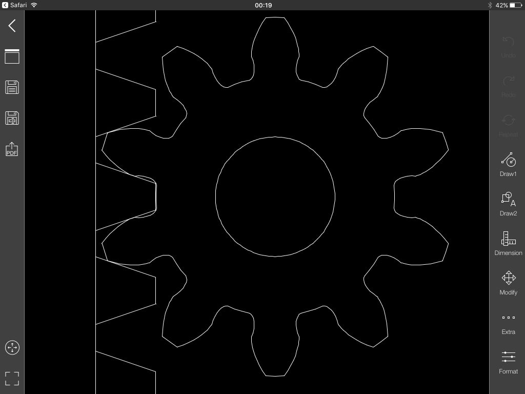
                        I've just been playing with this: **LINK**

                        http://hessmer.org/gears/InvoluteSpurGearBuilder.html

                        I think it might be just what you need to design a better pinion.

                        MichaelG.

                        .

                        img_1728.jpg

                        Edited By Michael Gilligan on 04/01/2018 00:25:49

                        #448267
                        Julian Saunders 1
                        Participant
                          @juliansaunders1

                          I made a new quill out of free cutting steel, 40mm to house tapered bearings, for the Uniamt, and like you, noticed the issue you describe, I used a horizontal cutter holder and ground the tip to the correct profile by eye and feel, I then used a Chester milling machine to hold the new quill whilst I cut the new rack, unfortunately I'm going to have to redo one day, as the Chinese seem to have used an imperial gear in THEIR quill rack, which approximates metric, but not anywhere near the accuracy I was working to, 0.001mm, over the length of the new quill (I made a new alloy vertical head to accomodate the new quill, which has more feed depth) . Moral, never trust a cheap Chinese fine vertical feed or quill !!

                          #448299
                          Martin Connelly
                          Participant
                            @martinconnelly55370

                            Are you planning to convert this to CNC. If so then a straight rack and pinion is unlikely to give a smooth linear motion, helical would help but would be hard to get acceptable mesh between the parts. As an alternative here is a link to a system that uses a ball screw that may be something that you could adapt to your needs.

                            **LINK**

                            Martin C

                            #512096
                            alex h.
                            Participant
                              @alexh-2

                              i done a cnc conversation.

                              i had the same problemes.

                              my solution:

                              grind a flycutter insert and cut the 10teeth gear or cut with modul 1 gearcutter no1 12 teeth gear. put your stepper to 1/8 microstepping and good.

                              but!

                              you can buy a dovetail-profil.

                              you need only a adapter to mount the dovetail profil column instead of the original. then you get more then 25mm way in Z.

                              #512098
                              alex h.
                              Participant
                                @alexh-2

                                ballscrews are ok but trapeziodal spindles with backlashnuts are cheaper and smaller.

                                dont forget the size of the unimat!

                                #512252
                                Jouke van der Veen
                                Participant
                                  @joukevanderveen72935

                                  Would a ballscrew be more accurate (less backlash) than a trapezoidal spindle with a (spring loaded) anti-backlash nut?

                                  #512349
                                  Jouke van der Veen
                                  Participant
                                    @joukevanderveen72935

                                    Alex,

                                    Did you remove your topic about twist of Unimat 3 support?

                                  Viewing 16 posts - 1 through 16 (of 16 total)
                                  • Please log in to reply to this topic. Registering is free and easy using the links on the menu at the top of this page.

                                  Advert

                                  Latest Replies

                                  Home Forums Manual machine tools Topics

                                  Viewing 25 topics - 1 through 25 (of 25 total)
                                  Viewing 25 topics - 1 through 25 (of 25 total)

                                  View full reply list.

                                  Advert

                                  Newsletter Sign-up