test bar – between centres

Advert

test bar – between centres

Home Forums Beginners questions test bar – between centres

Viewing 21 posts - 1 through 21 (of 21 total)
  • Author
    Posts
  • #220442
    Iain Downs
    Participant
      @iaindowns78295

      This is probably a silly question. My favourite sort!

      I'm about to embark on my first between centres turn. This is just a test bar (10mm BMS bar), but it's practice for my lathe spindle (40mm Bms – less inclined to ruin that…)

      I've done my best to centre the tailstock. It's about 5 though high (which I gather is 'normal&#39 and a couple of thou out horizontally which is about as good as I can get without building a screw based adjuster (I've already brought the lock bolt up through the top of the tailstock base as having it underneath is just ridiculous).

      I'd like to machine the whole length in one go, but I've got the lathe dog at the headstock end.

      I don't want to have a test bar which is good apart from the last 15mm and I don't want to cut off the last 15mm because then I loose my centre.

      What's the best way of approaching this?

      Also, mainly I've been using some left and right knife tools (basically it's more or less a right angle set with the main edge perpendicular to the work – I think that's what you call it). That won't fit without carving away the centre, so I'm looking to use a v shaped tool where the point of the v will touch the work. I'm not really sure what this is meant for, but seems like it might work. These tools are carbide tip and part of a set from one of the usual suppliers.

      Iain

      Advert
      #7961
      Iain Downs
      Participant
        @iaindowns78295
        #220446
        David Clark 13
        Participant
          @davidclark13

          Do one end between centres, turn round and do the other end at the same setting.

          #220448
          Speedy Builder5
          Participant
            @speedybuilder5

            I don't see an easy way on the lathe. It is likely that a 10mm diameter bar would need a travelling steady to produce a constant diameter over its length (without it bending in the middle). Bars of this diameter would normally be ground between centres on a grinding machine where the dead centre on the headstock drove the bar via friction and the tailstock end had a rotting centre – have a look on this site re live and dead centres.
            getting back to your problem, if the bar was short enough, you could turn up to the carrier dog at the headstock end, rough turn down to the last 0.2mm oversize, turn the bar around and clean up the other end. Then finish turn the last 0.2mm and then turn the bar around again for the other end.
            BobH

            #220452
            Michael Gilligan
            Participant
              @michaelgilligan61133

              As a practice turning exercise; swapping the workpiece end-for-end is fine [being a major advantage of between centres turning], but; if the idea is to produce a 'test bar' for future use, then with a tailstock that's 5 thou high and 2 thou offset, I see little chance of success.

              … Hoping that I have missed some important point.

              MichaelG.

              #220454
              Anonymous

                Use a longer than normal centre in the headstock and put an offset tapped hole in the headstock end of the workpiece. A screw in the offset hole can then be used to drive the workpiece with out getting in the way of the tool.

                Andrew

                #220455
                duncan webster 1
                Participant
                  @duncanwebster1

                  I've never seen why you'd want a test bar, but here's how I'd make one if I had to.

                  Get hold of a bit of precision ground mild steel.

                  face off both ends

                  hold one end in chuck (only by a short length, say 1/2&quot, support other end in fixed steady and centre drill

                  reverse and repeat.


                  The steady makes it impossible for the centre to be not concentric to the OD

                  Edited By duncan webster on 10/01/2016 18:52:32

                  #220463
                  JasonB
                  Moderator
                    @jasonb

                    If you grind up a tool something like this and don't go in too deep with the Ctr drill you can turn quiet small diameters, this is 4mm but I have gone down to 3/32"quite happily. BS0 drill and a small radius on teh end of the tool otherwise you risk your "V" shaped tool acting like a threading tool. You can also buy half centres that have a flat on the side to give extra tool clearance though I've never had the need to resort to one

                    If you are going to be using this test bar more than once then a reduced dia at the ends is not a bad thing as it will protect the finished dia from dameage if you drop the bar so you could have a short length of say 8mm dia at each end which would take a small dog.

                    J

                    #220466
                    Tony Pratt 1
                    Participant
                      @tonypratt1

                      You could turn say a 20mm length undersize to your test bar diameter and then grip with the lathe dog, turn as required running the tool out into the undersize portion.

                      Tony

                      #220469
                      HOWARDT
                      Participant
                        @howardt

                        The first thing, surely, is to use a precision test bar to set the tail stock so that everything runs true using fixed centres. Then turn a rigid bar to prove the setup. Using so small a diameter will cause more problems due to tool pressure and whip. Adding a steady puts another variant into the setup.

                        Howard

                        #220479
                        Ian P
                        Participant
                          @ianp

                          Rohm and probably other companies make 'Face Drivers' to do exactly what you are trying to do they are mostly used in CNC and production setups for finishing operations on mass produced motor and gearbox shafts etc.

                          What about the following..

                          Whilst there is not a lot of area on a 10mm diameter face, there is probably just enough to drill say a 1.5mm hole close to the edge of an end face and press in a projecting dowel to do the driving. The dowel would fit between the jaws of the chuck which I would have gripping a bit of bar turned conical as its potentially more accurate than a centre in the mandrel taper.

                          Ian P

                          #220538
                          Martin Connelly
                          Participant
                            @martinconnelly55370

                            I have just (between Christmas and the new year) turned a dumb-bell test bar between centres. The reason was to have a bar purely for setting the tailstock correctly and also to play around with a vertical shear tool. It also allowed me to use a newly acquired centre for the lathe headstock. After centre drilling I used a rusty old piece of steel about Ø25mm turned down the ends and centre sections to about Ø22mm with a carbide tipped tool (rough finish on this unknown steel). This left two 15mm bands for the fine machining. I cleaned these off with an ordinary HSS tool then used a HSS vertical shear tool to give a very fine finish. Measured the diameter difference of the test bands, adjusted the tailstock set over and repeated until the bands were about the same diameter. The biggest problem was adjusting the tailstock with worn slot ended grub screws. I have ordered some hex grub screw replacements (Colchester lathe spares!) to make it easier. I found that tightening the barrel clamp had to be done to the same point each time and the clamping of the tailstock to the bed was also able to change things noticeably. I found the best way to get the screws for set over adjusted was to calculate the adjustment required (half the difference on the test bands) as a degrees of turn for the screws and try to move them this amount.

                            I ended up with two test bands that are within 0.005mm of each other and a very smooth finish. I stopped at this point as I think that will do for what I want. I suspect the vertical shear tool or some fine abrasive will take off the difference if I wanted it better but this was an exercise in setting the tailstock more than anything else and the slot head screws made fine adjustment hard.

                            For the vertical shear tool machining was done at 400rpm 0.005mm per rev feed. I held a 1" paintbrush against the band when cutting, with suds applied to the bristles as required, This gave a thin film of cutting fluid and at the same time collected any fine particles that were being carried around the band. When the band was done each time there was a layer of very fine metal dust gathered on the brush looking like a silvery paste.

                            Martin

                            #222253
                            Iain Downs
                            Participant
                              @iaindowns78295

                              Thanks to all for the advice and my apologies for the delay in responding – the day job does get in the way…

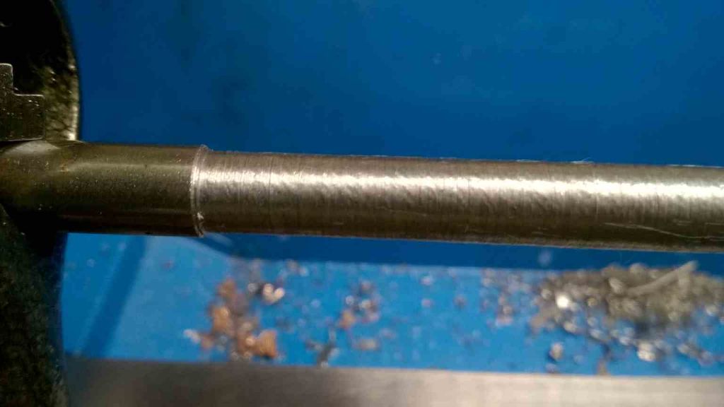
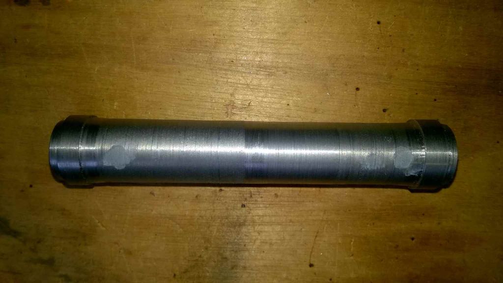
                              I can fairly describe my first attempt at turning between centres as .. well pretty grim. The (10×200) bar ended up resembling an ice cream cone rather more than silky smooth test bar. It was 1mm thinner at the chuck end, oval at the tailstock end and corrugated throughout. My shame is shown below

                              10mm between centres.jpg

                              Obviously a travelling steady is a minimal requirement! I also found that the tailstock was out. Most particularly it wasn't straight.

                              Anyway – after a little while off, I've had another go. THis time I believed I'd got the tailstock reasonably straight. Running the carriage along it with an indicator it was about a .03 mm further away from me at the tailstock end of the barrel (which was the limit of the adjustment such as it is). I got the centre in the tailstock fairly correct as well. Again .03 – .05mm out horizontally and .125mm vertically (which should affect the cut by less than .001mm according to my trigonometry!)

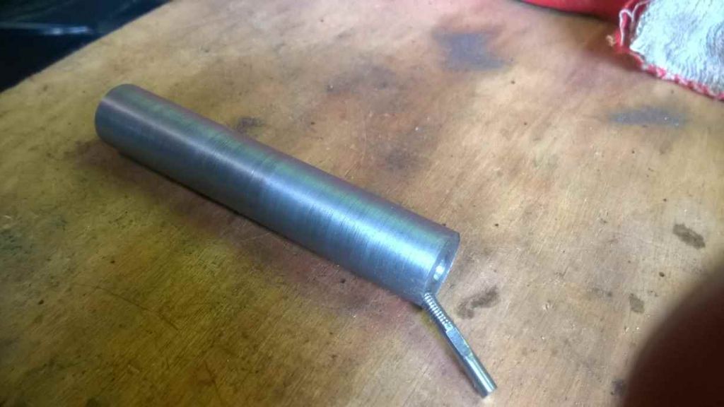
                              This time I used 20mm x 100mm and drilled and tapped a rod to put in the end to turn it per advice in this thread.

                              20mm between centres.jpg

                              This is better. It's 0.3mm diameter out (smaller at the head end) and although a bit groovy, quite a bit better than the first go.

                              before I started I found that centre in the headstock was about 0.1 mm out (the spindle has no measurable run out on the face or inside the taper socket, so I'm assuming it's the centre). I turned a new end on it to centre it.

                              When I finished I check the tailstock alignment and it was quite clearly out, which is most frustrating. I don't know what is making it go off, but I feel a tailstock adjuster is likely to be my next project. Which I will seek advice on in the next post (or this will get silly long).

                              Iain

                              #222262
                              Iain Downs
                              Participant
                                @iaindowns78295

                                Tailstock adjustment

                                This is what my tailstock looks like

                                tailstock front.jpg

                                The M5 bolt you see is not original. The original design requires that you pretty much have to take the tailstock off to tighten it up once you've got it set up. Needless to say, this is an excellent way of knocking it out of adjustment.

                                The basic approach is to leave the tailstock lightly tightened to the base and tappy tap until it's spot on then tighten it up. My skills with tappy tap seem restricted and getting the adjustment within .05mm is about as good as I can manage. Most often tightening the bolt slips it that far out again if with access from the top.

                                tailstock rear.jpg

                                In the rear there are two grub screws which adjust the alignment. I'm not entirely sure how they are supposed to work since they are bearing on to flat surfaces. They do a bit. However, even with the nearer screw tightened pretty hard the tail stock is still at an angle (towards me as it moves from the tailstock along the barrel. I suspect that adjusting with this tight isn't really helping the ease of adjustment.

                                So what to do?

                                I've seen some designs for forward and back tailstock adjusters (e.g. this)- basically a bracket and a stud thread. It would have to go at the back of the tailstock since it will get in the way of the carriage and slides if it were at the front.

                                My concern with making that is tapping cast iron. when I fixed my lathe I put some grease nipples in the headstock (M6) but had to redrill and tap to M8 because the thread stripped the first time I tried to take the grease gun off.

                                I expect I will want to use M5 fine for the bolt, so one turn is 0.5mm, (.01mm is 7 degrees – well beyond my aspirations!), however I suspect this is a bit fine for cast iron.

                                The other question I have is how to get the thread tight in the not so there is little backlash. My tap and die set is pretty poor quality being an anonymous set I picked up years ago. even tapping aluminium has made the M6 tap unusable (and the M5 die has been destroyed tapping the bar that turned my last between centres attempt)!

                                I'd also appreciate any advice on the angular adjustment. I suspect that adding a jib strip would help, but I think I need to do something more if I want to get the angular adjustment spot on.

                                All help, pointers and advice gratefully received!

                                Iain

                                #222265
                                Neil Wyatt
                                Moderator
                                  @neilwyatt

                                  If you set your tailstock as accurately as you can and the collars on your test bar are both the same distance from the end of the bar, then even with your inaccuracies the bar should come out OK as both collars are turned under exactly the same circumstances. That does assume you take the final cuts at the same setting after trying to get the collars as close as possible. This is how mine came out using this method, as near as my mike will tell me its 0.0003" out.:

                                  test bar.jpg

                                  #222266
                                  Phil Whitley
                                  Participant
                                    @philwhitley94135

                                    Hi Ian, where abouts in N Yorkshire are you?

                                    Phil, Driffield, East Yorks.

                                    #222271
                                    Iain Downs
                                    Participant
                                      @iaindowns78295

                                      Hi, Neil. I'm presuming that what you've done is to turn the bar round in the lathe so you are machining each end with the carriage in the same place?

                                      That's a good idea for a test bar. Now to work out how to get the tailstock spot on …

                                      Hi Phil – Pannal, near Harrogate.

                                      Iain

                                      #222313
                                      Neil Wyatt
                                      Moderator
                                        @neilwyatt
                                        Posted by Iain Downs on 23/01/2016 16:55:42:

                                        Hi, Neil. I'm presuming that what you've done is to turn the bar round in the lathe so you are machining each end with the carriage in the same place?

                                        That's a good idea for a test bar. Now to work out how to get the tailstock spot on …

                                        Exactly, and it compensates for a degree of tailstock mis-aligment.

                                        #222451
                                        Phil Whitley
                                        Participant
                                          @philwhitley94135

                                          Pannal, Damn, bit far out for me, I always forget about that bit of Yorkshire being "North as well!. It sounds toi me like you need to do a bit of work on the tailstock. Yes, it should be high, but maybe a thou or two at most. if you blue the bottom slides up you will probably find some high spots you can relieve with a scraper to get it down a bit, but the centering across the bed needs to be easy to adjust, and as near to spot on as you can get it.

                                          Phil

                                          #222459
                                          Neil Wyatt
                                          Moderator
                                            @neilwyatt

                                            You may find that the blue paint is causing the front of the tailstock to lift slightly

                                            Neil.

                                            #223562
                                            Iain Downs
                                            Participant
                                              @iaindowns78295

                                              sorry about the delay – the day job surely gets in the way of doing interesting stuff.

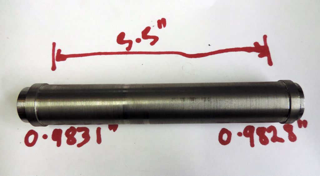
                                              This is my version of Neil's test bar. The end pieces appear to be the same diameter to within the limit of my abilities to measure it (a electronic caliper claiming 0.01 mm resolution).

                                              testbar.jpg

                                              On my first try I ended up with a noticeable difference despite not moving the cross slide. I put it back in and just re-cut about 4 times each end at quite a slow speed (200rpm?) each time taking the merest sliver off. Is that the right approach? I'm using a carbide knife tool,

                                              MY first go a the collars I did at high speed (<1000rpm and my first run in top on this machine), since I thought this would give a better finish. It really didn't and furthermore the lathe shook somewhat. Is this something which is acceptable? Do I try and balance the spindle and work piece with a dog bolt on the other side? Should I be trying to cut fast?

                                              Anyway. I'm quite pleased with this, though I'm scared that I will go out later in the week, re-measure and find that I was 1mm out in my measurements and it's all rubbish!

                                              Thanks for all the advice.

                                              Iain

                                              Edited By Iain Downs on 01/02/2016 20:28:59

                                            Viewing 21 posts - 1 through 21 (of 21 total)
                                            • Please log in to reply to this topic. Registering is free and easy using the links on the menu at the top of this page.

                                            Advert

                                            Latest Replies

                                            Home Forums Beginners questions Topics

                                            Viewing 25 topics - 1 through 25 (of 25 total)
                                            Viewing 25 topics - 1 through 25 (of 25 total)

                                            View full reply list.

                                            Advert

                                            Newsletter Sign-up