Stuart Twin Victoria: Advice & General Questions

Advert

Stuart Twin Victoria: Advice & General Questions

Home Forums General Questions Stuart Twin Victoria: Advice & General Questions

Viewing 25 posts - 51 through 75 (of 95 total)
  • Author
    Posts
  • #502763
    Dr_GMJN
    Participant
      @dr_gmjn
      Posted by Andrew Johnston on 22/10/2020 16:23:47:

      Posted by Dr_GMJN on 22/10/2020 16:10:02:

      So you couldn't simply change the ratio of the governor drive, to change the speed of the engine?

      Well you could, but I've never heard of it being done and I can't immediately see why one would want to. Enginemen of old would have been interested in getting the job done, taking the money and moving on. Not faffing about changing pulleys and belts. smile I doubt they would have had any accurate way of measuring engine speed anyway.

      Andrew

      It was just an idea, to achieve what I'd asked for.

      I wasn't suggesting that's how it was or should have been done, full size. I just wanted to know if there was some way to vary the speed of a governor-equipped model engine; slow – medium – high, and to show how if you load the flywheel (within each setting), the governor attempts to correct the speed.

      On a model with a spring band driven governor it would be a simple case of slipping the band from one part of a stepped pulley to another. If it didn't work out, fine, swap the pulley to a single diameter and you've lost nothing.

      Advert
      #502769
      Dr_GMJN
      Participant
        @dr_gmjn
        Posted by Ramon Wilson on 22/10/2020 16:26:47:

        Doc G – you will certainly not be the first to want to have a properly 'working' governor and many have tried before but like most things as matters are scaled down the physical effects don't scale with them.

        As Andrew aludes – it's a bit of a holy grail. But he's right, a governor is just that – a device to govern the set speed the engine is designed to run at. Load comes on governor gives more steam – Load comes off vice versa. They aren't designed to work through varying speeds and they don't work as well on air. Only this morning I have my latest build running – very happy with it just on one of two cylinders. It will run through a range of speeds depending on the stop valve setting. Couple up the governor and it's affect is instant – hunting back and forth as speed increases and decreases. Though the spring is to design first thoughts are that it obviously needs to be much stronger to over come this problem. If the governor is to work effectively the speed will be set by it and not by the stop/inlet valve.

        The Lang Bridge Double Diagonal engine built has no governor. When I made it I phoned the supplier to ask why. None on the original came the answer – it was designed to drive a calico printing press which required varying speeds depending on (the printed) design. The full size engine was controlled by the stop valve.

        As I prefer to run my engines at a slower pace the governor is fundamentally ineffective – it's just nice to see it 'working' – If this latest one proves to affect the smooth running I'm afraid it's going to be restricted to 'visual' only.

        Personal view is if the governor will give a bit more when drag is applied to the flywheel it's working but if it's having a detrimental effect on performance then it's cosmetic only.

        Ramon

        Thanks Ramon. a surprisingly difficult decision – working governor, or cosmetic. I know that I'll at least have to try to get one working I suppose.

        Do you by any chance have plans that incorporate an rc engine barrel type valve? At first glance, the Princess Royal articles describe a butterfly valve. TBH I don't fancy my chances of being successful with that, or at least I fear for my mental health if I resolved to get it working…

        Regarding the "hunting" issue – isn't this more of a damping problem than a spring rate problem?

        #502823
        Anonymous
          Posted by Ramon Wilson on 22/10/2020 16:26:47:
          Couple up the governor and it's affect is instant – hunting back and forth as speed increases and decreases.

          Hunting can occur as a result of the governor being too sensitive, but it can also be the result of unwanted friction in the valve operating mechanism effectively creating a deadband.

          Andrew

          #502832
          Ramon Wilson
          Participant
            @ramonwilson3

            Hi Andrew, I think its more likely the former than the latter.

            It's early days as yet as to what the cause actually is. The movement of all the linkage is very free but positive with no slack. It's a Hargreaves type and the weights do have a bit of play before they impinge on the spring but as they are not in contact at that point I can't see that as being a reason.

            If the engine speed is increased considerably then effect decreases in proportion which reinforces my earlier point of a governor 'setting'the engine speed and not the stop valve.

            At this stage however I'm not too bothered as to the cause as there is still the second LP cylinder to couple up to the first and get the valve gear in tune with the HP

            Dr G – I don't have any plans or even drawings of the 'throttles' I fitted. I just drew them up at the appropiate time to fit inside the valve body as designed – it is no more than a rotary motion – getting the areas right in conjunction with the motion available and the desired speed is another matter. Hence my ready acceptance to see the governor as more cosmetic than functional.

            Don't let me put you off by that – if solving such problems is the type of challenge you enjoy then by all means try – just don't be too disappointed in the result if it doesn't quite turn out to what you hope.

            Regards – Ramon

            #502833
            Dr_GMJN
            Participant
              @dr_gmjn

              So I’ve read all the Princess a Royal articles now. I think I can at least give it a go as per TC’s description and plans. There are however a few things that I know will be difficult for me. Mainly these are around making tools. Apart from the eccentric groove tool on the 10V (which was very easy to make), I’ve no experience of making HSS tooling. So the keyway tool and holder, the flywheel rope groove tools and the internal groove tools for the eccentric straps are all a mystery. Also, are carbide straight-through boring bars available? Any advice – as ever – is appreciated.

              By the way, I smiled when I read the final part of the governor articles just now: CT mentions that the equilibrium engine speed can be adjusted by changing the governor drive pulley diameters, or by hanging small weights on the actuating levers, ie what I wanted the option of doing. Whether I’ll be able to replicate the success of Ramon’s and CT’s governed engines remains to be seen.

              #502838
              Ramon Wilson
              Participant
                @ramonwilson3

                I'm afraid I won't be much help where carbide tooling is concerned but I can where HSS is. A bit early to go into specifics as yet but have used nothing else and home made carbon steel cutters for many years.

                Remember – Experience only comes with practice.

                Making tooling is part of that. Once you've made your 'through hole' boring bar you won't need to again and so on.

                Help is at hand on anything like that but it's probably best to ask when you require it.

                Happy to help at any time as I'm sure others will be

                That's it for today – the duvee beckons!

                #502857
                JasonB
                Moderator
                  @jasonb

                  I also mentioned counter weights earlier as well as adjusting spring tension as ways to adjust the governor which alters the load the centrifugal force from the weights needs to overcome, pulley changes would just be a way of altering the centrifugal force against a fixed load. As you say you want gear/shaft drive the pully option is not going to work here anyway.

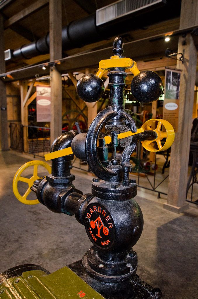
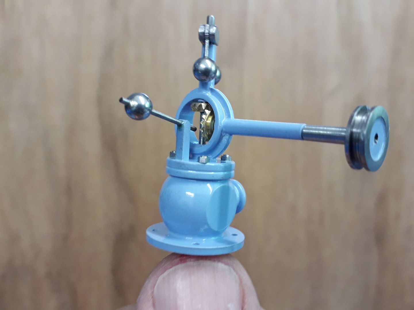
                  The problem still comes down to scale, I recently modelled an engine that had a Gardner style governor, these use a weight on an arm to set them.

                  I decided a show governor was the best I could manage as the weight was only 3/16" diameter, arm 1mm dia and had I wanted it to work that thin rod going down to actuate the internals would have been about 0.3mm and the screw that locks the weight on the shaft M0.4

                  #502867
                  Ramon Wilson
                  Participant
                    @ramonwilson3

                    Very nice work as usual Jason yes (is that off the rocking valve engine?)

                    It supports my view on scaling – those balls on the full size would have a fair amount of mass but 3/16 balls would not quite be in the same league eh?

                    First line of approach will be a stronger spring but that's a day or three off yet.

                    #502868
                    Dr_GMJN
                    Participant
                      @dr_gmjn

                      That’s a beautiful bit of work Jason. Yes I didn’t want a band drive because I get the impression from my old Mamod and Wilesco engines that they have a lot of spring, and might just make a marginal governor unworkable (and mine will probably be marginal at best tbh). I’ve not decided yet.

                      Thanks Ramon, I guess I’ll ask again as and when about tooling.

                      I’ve got to now amend my materials list in line with the P.R., and I’ll place an order next week for what it’s worth. Looks like there was an error in the list, So I can probably knock £20 worth of bronze off the price.

                      I’ve then got some machine work to do (ML7 wide bed conversion, settable dials, thrust bearings and a threading handle, and sort out the dodgy head strut on the mill). All being well Ill make a start on the P.R. early next year.

                      Cheers all.

                      #502871
                      Anonymous
                        Posted by Ramon Wilson on 23/10/2020 08:49:51:

                        It supports my view on scaling – those balls on the full size would have a fair amount of mass but 3/16 balls would not quite be in the same league eh?

                        Mass scales as a cube law. So on my 4" scale engine I'm down by a factor of 27 on mass. It's the main reason why scale governors that rely on mass for sensing are difficult to get working. I've done my best to ameliorate the problem by making the balls slightly oversize and making them from tungsten alloy. Even the screw holding the ball halves together is made from a tungsten TIG electrode. Platinum was ruled out on cost grounds. smile

                        Andrew

                        #502876
                        Ramon Wilson
                        Participant
                          @ramonwilson3

                          Dr G

                          I was never happy with the appearance of the belt I used on my Twin Vic – it was made from o ring material joined with super glue. It was easy enough to make and it worked ok – for a time – but would often break during running at a show. Incidentally that did show that the engine was governed to a degree as it would instantly race away.

                          I was given a drive belt from a tape deck that I used on the Waller engine – flat in section, about 4mm wide and less than a mill thick it hasproved ideal – it's still the original one. I used a similar but smaller version on the McOnie and again a wider and slightly thicker version on the latest engine. Black in colour theres a degree of stretch but not enough to be 'elastic' and importantly they appear unaffected by the oil that's always around. Lots to choose from on Ebay.

                          If you intend to go down the HSS route you do need a decent off hand grinder but you don't need to buy in lots of HSS blanks. If you use throw away cutters on your mill then the shanks of these make superb lathe tools held in mild steel holders – after all its only the very tip of the tool that is in use – as long as you have that right whats behind it doesn't matter. Much easier that grinding away 5/16 or 3/8 square blanks – they are easily held in a round holder by a grub screw for grinding and cheap – free in fact if the cutter has had a useful life.

                          If you don't have any – I have plenty of spare

                          I did consider using a heavy metal Andrew as the weights are quite small but in the end decided it wasn't really worth the effort or expense – this will work out fine in the end I'm sure even if it is only just going 'round' wink

                          Regards – Ramon


                          Edited By Ramon Wilson on 23/10/2020 09:32:47

                          Edited By Ramon Wilson on 23/10/2020 09:35:36

                          #502878
                          JasonB
                          Moderator
                            @jasonb

                            You have got it easy Andrew with a factor of 27, if we take the height of an average handrail as 36" and the ones on Princess Royal stand 2" tall that makes for a 1/18th scale model so the factor is 5700! No wonder the governor scales out at 6ft tall with what would be 9" dia balls.

                            #502912
                            Anonymous

                              Well if you will persist with all this tiddly stuff what do you expect? smile Incidentally I make 18³ equal to 5832.

                              I build big stuff as an antidote to work electronics. The current job is going to require using ICs that are 0.8mm square with 4 solder balls underneath on a 0.4mm pitch. For space reasons we will need to use 0201 passives; that's 20 thou by 10 thou. I can't even see the darn things without a magnifier.

                              Andrew

                              #502914
                              Anonymous

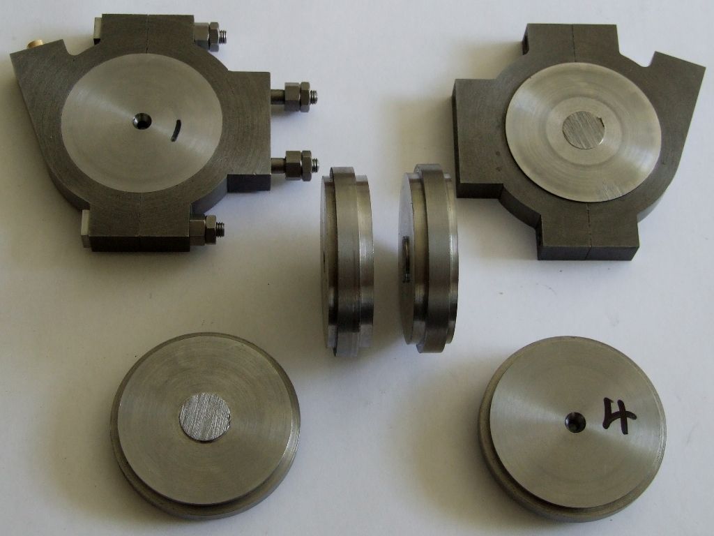
                                I use insert tooling for general turning but use a lot of HSS tooling for specials. On the repetition lathe I exclusively use HSS toolbits as that is what it was designed to use. The internal grooves in these eccentric straps were machined with a HSS tool using the numbers on the dials rather than measure and cut:

                                eccentric strap oiler.jpg

                                Likewise the mating sheaves were machined with a HSS tool:

                                eccentric sheaves.jpg

                                I used a groove micrometer as a sanity check on the groove widths.

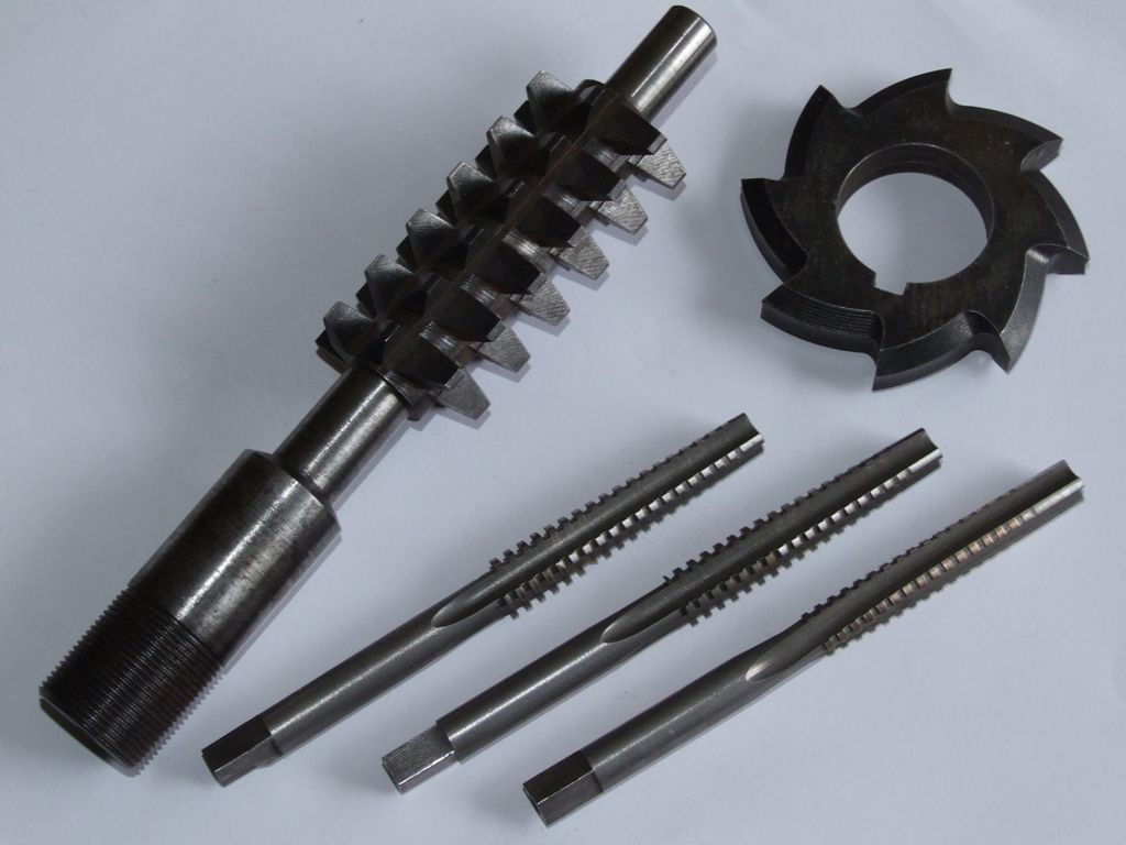
                                Like Ramon I make one off tooling using silver steel and gauge plate:

                                cutting tools.jpg

                                If I've done it then I'm happy to explain how, if I haven't then I keep quiet.

                                Andrew

                                #502918
                                JasonB
                                Moderator
                                  @jasonb
                                  Posted by Andrew Johnston on 23/10/2020 12:11:16:

                                  Well if you will persist with all this tiddly stuff what do you expect? smile Incidentally I make 18³ equal to 5832.

                                  Andrew

                                  Ah, I forgot you were back Andrew and should have put "approx" as I used 0.056 as 1/18thblush

                                  Rather you than me on the solderingcool

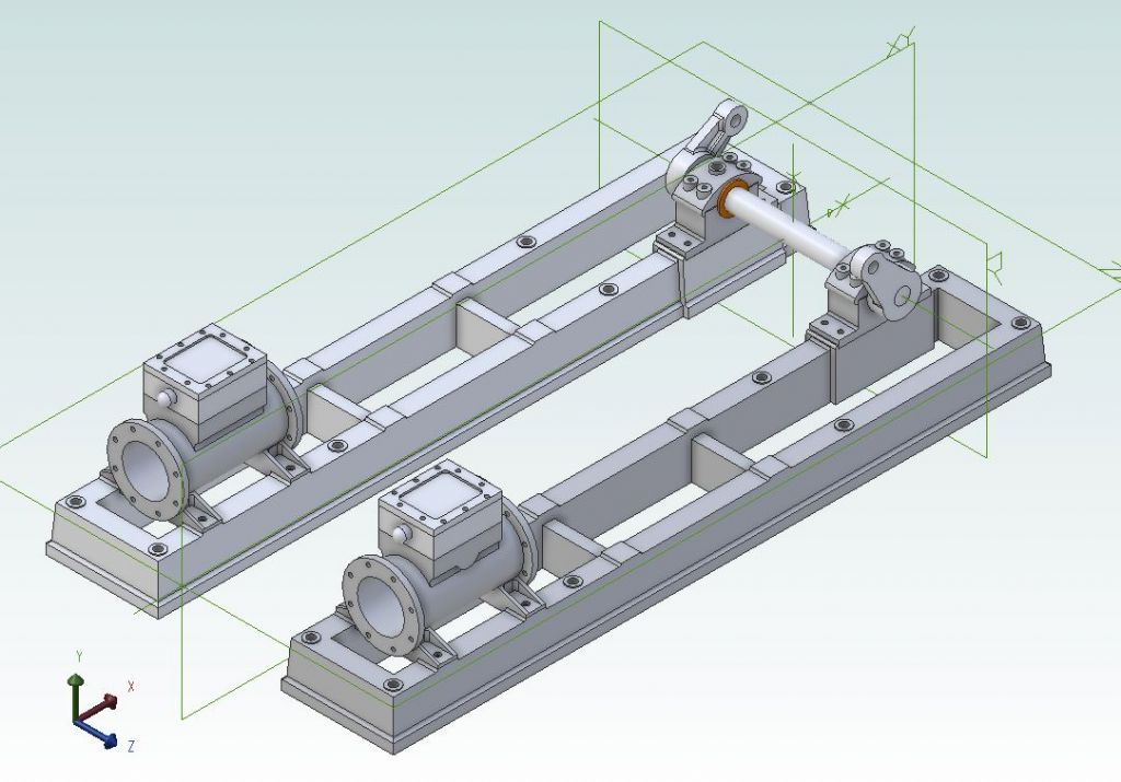
                                  I did have a bit of a doodle last night, Vicky and her twin sister in the early stages, all fabricated.

                                  vicky 1.jpg

                                  #502924
                                  Dr_GMJN
                                  Participant
                                    @dr_gmjn

                                    That looks good Jason. The difference I have is mainly in the bearing mounts.

                                    I've been quoted for 25mm x 10mm Al.

                                    I was thinking to have an 8 mm high parallel side around the base at 10 mm wide, a 15 mm high tapered section above that, then another 2 mm high parallel section at 9.53 mm, which would match the 3/8" wide bearing blocks. This 2 mm high section would be milled back along the lengths to form the bearing and cylinder mounting pads. By my reckoning this would then give an approx. 1.8 degree taper on the outside faces to represent some draw.

                                    I would have to figure out how to cut this angle accurately though.

                                    However, I do like the look of the plinth around the base – and how you've modelled it in general.

                                    I like the idea of not having mounting lugs, which look out of scale and a bit ugly. Is the intention on yours to use studs up through from the base and put nuts on the top?

                                    Thanks.

                                    #502929
                                    JasonB
                                    Moderator
                                      @jasonb

                                      I'd based my drawing on being able to pick up some imperial 1/2" x 1" aluminium and that would give me a 10mm width at the top allowing for draft and the flaired foot. Another option if you can't get that size or a slightly thicker metric one is to use a separate plate on the bottom as shown here (CNC not required) or rather than having the moulding at the bottom it can be cut into the top outer corner with a simple home made cutter.

                                      Yes the base would be held down by long studs into the base with nuts bearing on raised round bosses. These bosses are just thick "washers" that are loctited into a shallow counterbore and then a fillet of filler run around the edge to give the cast look.

                                      #502962
                                      Dr_GMJN
                                      Participant
                                        @dr_gmjn

                                        OK so I can get 1” x 1/2” aluminium. I wonder if I could use the fly cutter with a 0.8mm tip radius insert to simultaneously form the angled side, and the step with its corner fillet?

                                        I might be able to make an angled jig out of steel, and secure the aluminium to it with screws through the steel into the Inner (flat) faces of it.

                                        #502999
                                        JasonB
                                        Moderator
                                          @jasonb

                                          Flycutter will do the sides easily but nay be a bit harder to set up for the ends, probably have to do the end pieces before assembly and sort out a way to the the ends of the sides then a final file all 3 pieces flush after the JB weld has gone off.

                                          Did I show the simple way to angle a vice for this sort of job? easy to work out height of packing if you know angle and distance between points of contact.

                                          #503007
                                          Dr_GMJN
                                          Participant
                                            @dr_gmjn

                                            Yes, my intention was to taper all the parts separately and then assemble and file/fill as necessary. My vice isnt that wide, so I actually thought the long sides would be an issue with the ends deflecting. Hence the steel backing idea.

                                            One thing my supplier can’t get is crankshaft material : 7/16” diameter in a steel I’ll be able to cut a keyway in. I don’t really want to turn bar down for it. Any suggestions on type? Maybe something that’s ground or at least made to decent enough tolerances?

                                            Thanks.

                                            #503009
                                            JasonB
                                            Moderator
                                              @jasonb

                                              Precision Ground Mild steel has a similar finish and size tolerance to silver steel and is easier to work, M-Machine list it in 7/16" and go to the trouble to wrap it so not damaged by other materials in the same order.

                                              #503014
                                              Dr_GMJN
                                              Participant
                                                @dr_gmjn
                                                Posted by JasonB on 23/10/2020 19:55:04:

                                                Precision Ground Mild steel has a similar finish and size tolerance to silver steel and is easier to work, M-Machine list it in 7/16" and go to the trouble to wrap it so not damaged by other materials in the same order.

                                                I’ll order some next week along with the rest.

                                                Looks like I might make a start a lot sooner than I thought.

                                                #503206
                                                Dr_GMJN
                                                Participant
                                                  @dr_gmjn

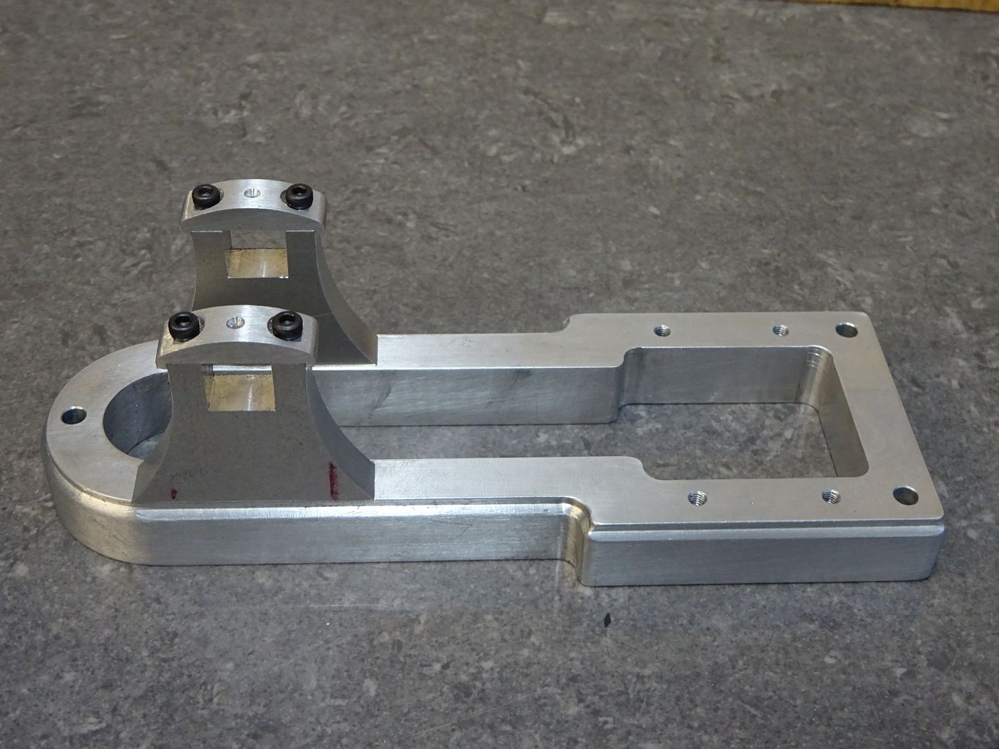
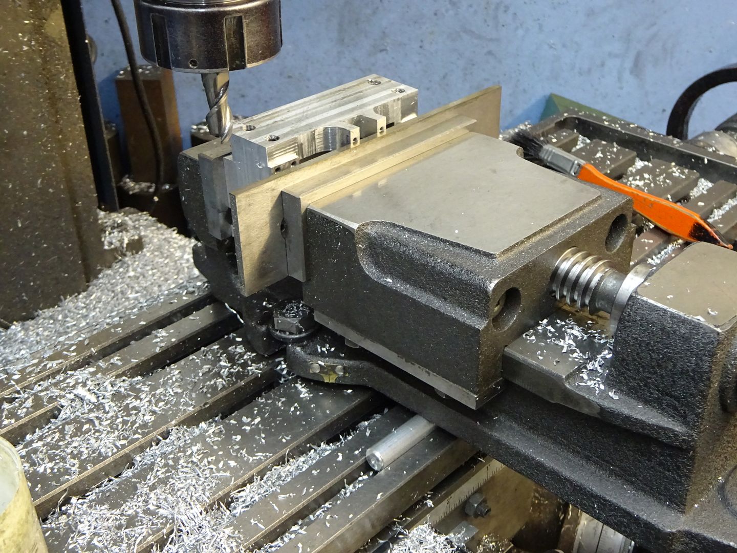
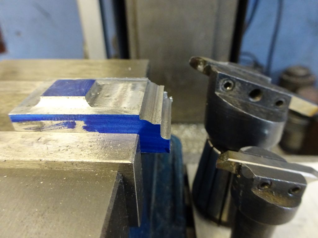
                                                  So this morning I had a play about with fly-cutting some scrap aluminium.

                                                  I used Jason's vice tilt method, which worked well, but I think a longer workpiece will definitely need more support – somehow:

                                                  I had to grind the back of my toolholder (under the insert) a bit, because it was scraping on the workpiece.

                                                  This was just a random angle, I think it looks OK, perhaps bit shallow. I used to design steel castings for offshore oil platform jackets, and it was always about a 3 degree taper for those.

                                                  Here it is de-burred and after a light going over with wet and dry:

                                                  And painted with primer:

                                                  I think the finish is fine – I was pleasantly surprised with how it machined since I only have 0.8mm radii inserts for cast iron and steel.

                                                  It's going to take some very careful setup and marking out once I've figured out a holding method, but at least I know it's doable from my point of view.

                                                  Regarding the taper on the ends: I guess I could assemble the whole lot with machined sides and plain ends, then clamp down with the opposite end raised slightly to give the draw angle, then mill the sides vertically? This would give a fairly stiff structure for machining, and I could mill the ends of the long sides and the ends faces simultaneusly, guaranteeing they match. Then again I'm still really struggling with chatter with side milling, even on aluminium.

                                                  The "start next year" idea seems to have gone out of the window. As with my scale modelling projects, I always tell myself I'll take a break and just enjoy the completed stuff I've done, but for some reason the allure of next project is always irresistable.

                                                  #503274
                                                  JasonB
                                                  Moderator
                                                    @jasonb

                                                    You should be able to move the side along in the vice and go at it in two or three stages, I've certainly dome long items like that.

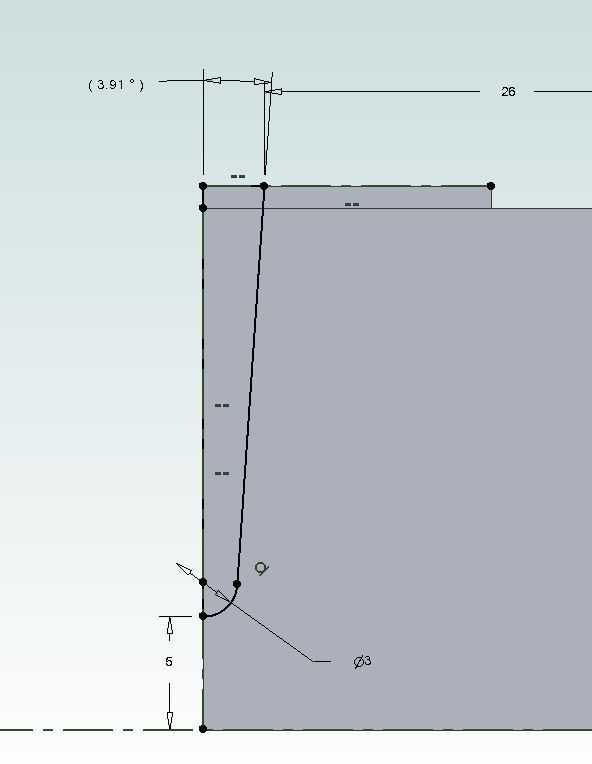
                                                    I went with a larger 1.5mm radius and to give the 10mm width at the top that I'm using the angle comes out at just under 4deg

                                                    vic base sweep.jpg

                                                    It's not too hard to grind up a round nosed tool bit to go into a small flycutter, another option is to freehand grind the corners of a blunt milling cutter to the radius you want. Does not have to be bang on as after all we are trying to replicate castings that are not perfect so a bit of hand work is a good thing that is why I usually nock off the external corners with a file rather than going for the more regular finish that a corner rounding milling cutter gives and will also run a Dremel over the surface for a bit of texture depending on scale.

                                                    I should really be directing you to a copy of my book but here are a couple of examples of mouldings produced from basic freehand ground tools.

                                                    photo 89.jpg

                                                    I would get all the parts to length first, drill and tap the ends of the four cross pieces and also drill and counterbore the sides first. Then setup to mill the long pieces to profile followed by the end pieces which can be done the same way. Then JBWeld and screw it together on a flat surface such as the mill table – a sheet of thin plastic cut from a bag will stop the work getting stuck to the mill table.

                                                    Once the JBW has gone off (at least 24hrs) skim the bottom and then the top, while setup for the top you can reduce heights to leave the mounting bosses and drill & tap those. Also if using through studs for mounting these can be drilled and a counterbore added for the round bosses.

                                                    Lastly hold by the sides in the vice at a slight angle so that most of the protruding ends of the side pieces can be side milled off then finish with a chalked file. lastly ease all external corners that would have been cast with file then Emery cloth. Before painting fill assemble screw holes with filler and add any internal fillets with filler or two part putty.

                                                    #503281
                                                    Dr_GMJN
                                                    Participant
                                                      @dr_gmjn

                                                      Thanks Jason. Moving in the vice sounds like a plan.

                                                      So were inevitably back to grinding tools! It’s something that seems a black art, and it genuinely makes me reluctant to have a go. I have tried it, with little success. Maybe I need a new type of bench grinder wheel. I know there are pages of advice in books and online, but whenever I try it…something’s been wrong somewhere!

                                                    Viewing 25 posts - 51 through 75 (of 95 total)
                                                    • Please log in to reply to this topic. Registering is free and easy using the links on the menu at the top of this page.

                                                    Advert

                                                    Latest Replies

                                                    Home Forums General Questions Topics

                                                    Viewing 25 topics - 1 through 25 (of 25 total)
                                                    Viewing 25 topics - 1 through 25 (of 25 total)

                                                    View full reply list.

                                                    Advert

                                                    Newsletter Sign-up