New here, just bought myself a Myford ML10 :)!

Advert

New here, just bought myself a Myford ML10 :)!

Home Forums Introduce Yourself – New members start here! New here, just bought myself a Myford ML10 :)!

Viewing 19 posts - 26 through 44 (of 44 total)
  • Author
    Posts
  • #550443
    Redsetter
    Participant
      @redsetter
      Posted by Higgins1994 on 19/06/2021 12:05:19:

      ah ok i may as well stick to the setup ive got then and try and seal them a bit better, as long as i know their getting oil to the bearings i shall rest easy ill have a look around for a dial for the leadscrew that is a good shout, myford have them but they are not resettable

      It is not difficult to make a leadscrew dial.

      Mine is turned from an aluminium blank about 3/4" thick and bored to be a loose fit over the shaft of the leadscrew handle. Fitted between the shaft and the dial is a wide, C section collar of springy brass, rather like a very wide piston ring, which provides a friction drive to allow for resetting. Then you need to devise a suitable reference mark on the leadscrew bearing housing.

      There are various ways of putting the graduations on if you don't want to engrave them, if you use a pre-printed scale you have to make the diameter of the dial to suit. It is, though, quite useful even with only one line for "zero" because often that is all you really need to know.

      Advert
      #550446
      Howard Lewis
      Participant
        @howardlewis46836

        Made na Leadscrew dial for my ML7, from a picador handwheel.

        Skimmed the OD to produce a flat surface. Smuggled into work on a Saturday morning, and spent the time in Standardsn Room with a Height Gauge, on the optical dividing head, scribing 125 lines onto the flat surface.

        (8 tpi Leadcsrew )

        Bolted a bit if flat plate onto the rear Leadscrew bearing housing to act as a datum.

        Something similar can be arranged, no doubt for mthe ML10

        Howard

        #550460
        ega
        Participant
          @ega

          The Super 7 has a leadscrew dial as standard which I find useful but it would be better still if the dial were re-settable.

          Hemingway Kits have a design for thrust bearings for the leadscrew which incorporates re-setting via a pinch screw; has anyone experience of this?

          #550461
          derek hall 1
          Participant
            @derekhall1

            I fitted the Hemingway upgrade to the leadscrew dial on my Myford S7 some years ago. It's an easy and useful upgrade but I find the resetting pinch screw always seems to end up in the opposite side to the user I.e. in the most inaccessible position!

            Regards

            Derek

            #550487
            Higgins1994
            Participant
              @higgins1994

              that sounds like a plan redsetter will definatly be giving that a go, in the box of stuff that came with the lathe was a kind of make shift indexing device – basically a 3 jaw chuck mounted on a gear with a tapered bolt that can be tightened between each tooth as its rotated, may be of some use to scribe some incriments around

              ive been drilling through my leadscrew clutch today but unfortunatly i dont have much in the way of drills over 13mm :/ the closest i can get is 15.9mm then the next up would be 16.20, would this be a bit too much clearence on the leadscrew or could i get away with it :/?

              #550492
              ega
              Participant
                @ega
                Posted by derek hall 1 on 19/06/2021 16:29:18:

                I fitted the Hemingway upgrade to the leadscrew dial on my Myford S7 some years ago. It's an easy and useful upgrade but I find the resetting pinch screw always seems to end up in the opposite side to the user I.e. in the most inaccessible position!

                Regards

                Derek

                Thanks for this very interesting point. I will ponder on how the difficulty might be overcome.

                My reason for mentioning this modification (which seems applicable in principle to the ML10) was that I had some doubts over the ability of the pinch screw to withstand the torque from the rotation of the handle without slipping.

                #550495
                Redsetter
                Participant
                  @redsetter
                  Posted by Higgins1994 on 19/06/2021 19:46:48:

                  that sounds like a plan redsetter will definatly be giving that a go, in the box of stuff that came with the lathe was a kind of make shift indexing device – basically a 3 jaw chuck mounted on a gear with a tapered bolt that can be tightened between each tooth as its rotated, may be of some use to scribe some incriments around

                  ive been drilling through my leadscrew clutch today but unfortunatly i dont have much in the way of drills over 13mm :/ the closest i can get is 15.9mm then the next up would be 16.20, would this be a bit too much clearence on the leadscrew or could i get away with it :/?

                  The leadscrew is 5/8" o.d. so around 15.875mm. Drills tend to cut oversize anyway – strictly speaking it ought to be reamed to the final size – but I should think you would get away with a 15.9 drill if you have no alternative.

                  When I made my leadscrew clutch I bored the sleeve oversize and put in some Oilite bushes.


                  Edited By Redsetter on 19/06/2021 21:37:43

                  #550544
                  Redsetter
                  Participant
                    @redsetter

                    Joshua,

                    Not the best photos but these may be of interest.

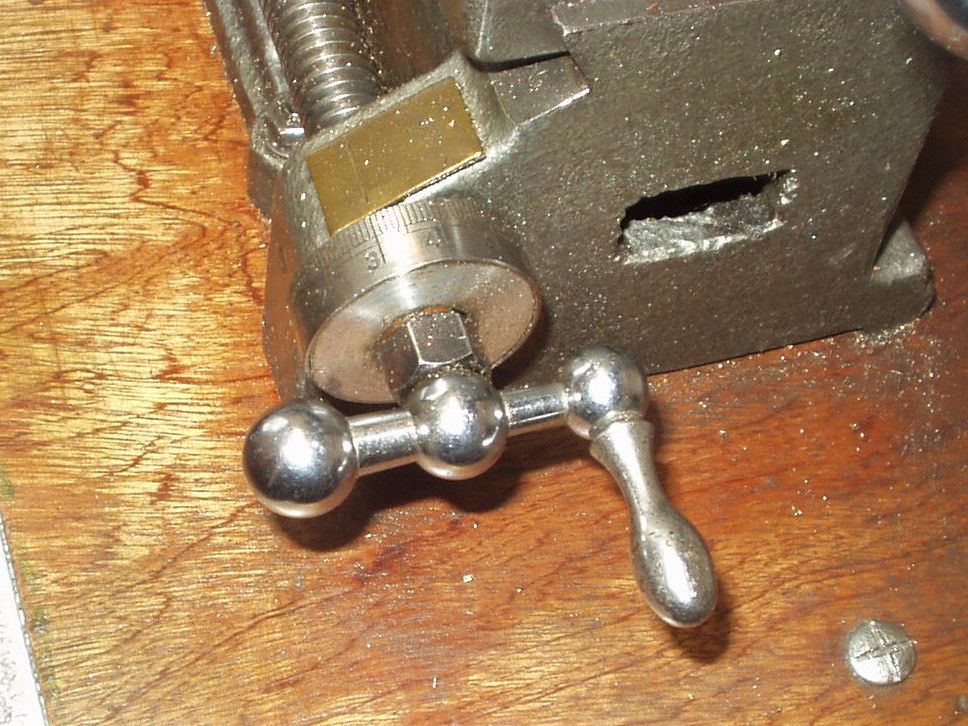
                    Leadscrew dial – With an 8tpi leadscrew 1 revolution = 125 thou, so I made the circumference of the dial 125mm and used a section cut from a thin steel rule as the scale, so 1mm on dial = 1 thou. It is accurate enough, and works for me.p1010007 (2).jpg

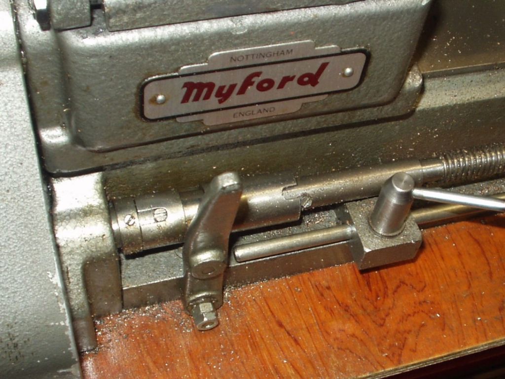
                    Clutch – the lever obviously is Myford, otherwise from scratch. The lever pivot is mounted on a length of steel angle, shaped to a close fit with the bed and retained adequately by just one holding-down bolt. The lever isn't essential as the clutch should only be moved when stationary. Carriage stop mounted on the RH end of the angle piece – this is another easy thing to make and very useful.p1010009 (2).jpg

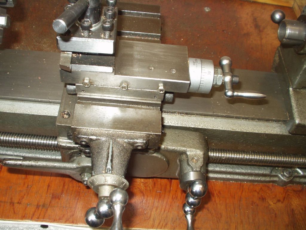
                    Top slide/toolpost – this was missing from the lathe when I bought it, so I adapted a Mini – lathe assembly. This needed quite a bit of modification but works well and cost very little. p1010007 (3).jpg

                    #550600
                    Engine Builder
                    Participant
                      @enginebuilder

                      A very useful mod is a clutch on the spindle. I made mine years ago from detilas published in Model Engineer.

                      You can see it around 1:10 time scale in this video.

                      #551208
                      Higgins1994
                      Participant
                        @higgins1994

                        finally got round to fitting my leadscrew clutch today after drilling out to 15.9 it was still to small so i ended up modifying my boring bar to fit and shaved off a thou at a time till it was a good fit, made a floating die holder to put a 1/4" thread on a couple of studs and got it all together. it all operated very smoothly im quite chuffed!

                        your photos arent working unfortunatly redsetter :/ shame as im interestedto see your leadscrew dial, i had in my head to weld up a bracket perpendicular to the diy indexting device that came with the lathe so i could scribe each incriment around the edge but the sprocket is only 72 tooth which would work out at 1.73 thou per incriment so not ideal haha :/

                        the spindle clutch is an interesting one, why is that an advantage :/? surely it is best to minimize the time that the motor is running? it seems that turning it on and off is just as fast as engaging/disengaging. is there a surge when starting/stopping motor that is best avoided or something?

                        so far i have been running it without any change gears on it, im going to put them on tomorrow so i can use the clutch/ power the leadscrew but according to the manual that means i have to topup the oil nipple on the side of one of the headstock pulleys, how could one keep this lubricated without a myford (or any) oil gun? where does it go from this nipple as its only to lubricate the change gears so cannot figure out how that works haha :/

                        #551214
                        Howard Lewis
                        Participant
                          @howardlewis46836

                          I think that the idea behind a clutch between motor and lathe is so that the motor is spared repeated starts.

                          Single phase motors, in particular do not like being started frequently. The heavy current draw on start up generates heat, so frequent starts cause the heat to build up.

                          Shouldn't be too much of a problem with normal use, and a low load factor.

                          Howard

                          #551219
                          Redsetter
                          Participant
                            @redsetter

                            Joshua, I'll reload the photos here.p1010007 (2).jpgp1010009 (2).jpgp1010003 (1).jpg

                            Hope that helps.

                            As Howard says a clutch on the motor isn't really necessary for our sort of use, but is a nice luxury, although a little difficult to arrange on the ML10 because of the countershaft design.

                            Edited By Redsetter on 25/06/2021 00:30:50

                            Edited By Redsetter on 25/06/2021 00:32:33

                            #551225
                            Redsetter
                            Participant
                              @redsetter


                              so far i have been running it without any change gears on it, im going to put them on tomorrow so i can use the clutch/ power the leadscrew but according to the manual that means i have to topup the oil nipple on the side of one of the headstock pulleys, how could one keep this lubricated without a myford (or any) oil gun? where does it go from this nipple as its only to lubricate the change gears so cannot figure out how that works haha :/

                              The oil nipple on the headstock pulley is to lubricate the pulley bearings while the back gear is in use, as distinct from the change gears which drive the leadscrew. With the back gear engaged (remembering to disconnect the bull wheel) the pulley rotates on the headstock spindle.

                              Going back to the leadscrew dial you could possibly index it using the 65 tooth bull wheel, which would give you 5 thou increments which would be quite useful and wouldn't take too long. 

                              Edited By Redsetter on 25/06/2021 07:57:04

                              #551230
                              Higgins1994
                              Participant
                                @higgins1994

                                ah that makes a lot more sense ill be very honest i thought they were the same thing (back/change gears) shows how much i have to learn still haha

                                i like the dial defo on my todo list, i presume you made the brass shim then bored the dial a bit at a time untill you got a good fit or did you work to a specific clearance?

                                #551231
                                Higgins1994
                                Participant
                                  @higgins1994

                                  going back to the subject of oilers i just found this, wouldnt mind making a set at some point …..

                                  homemade wick feed oilers

                                  im sure others will know about his channel already but theres some great vids

                                  #551233
                                  Redsetter
                                  Participant
                                    @redsetter
                                    Posted by Higgins1994 on 25/06/2021 09:10:33:

                                    ah that makes a lot more sense ill be very honest i thought they were the same thing (back/change gears) shows how much i have to learn still haha

                                    i like the dial defo on my todo list, i presume you made the brass shim then bored the dial a bit at a time untill you got a good fit or did you work to a specific clearance?

                                    I can't remember exactly, but yes, basically just made it to fit.

                                    #551239
                                    Howard Lewis
                                    Participant
                                      @howardlewis46836

                                      If you haven't got an oil gun, buy a Reilang, rather than a Myford one.

                                      The difference is that the Reilang does not leak as you lubricate the various points on the lathe, and that it works at any angle.

                                      Howard

                                      #551314
                                      Higgins1994
                                      Participant
                                        @higgins1994

                                        ah ok ill bear that in mind will be ordering one when i get paid they seem to be quite cheap if bought from germany

                                        i have noticed that im having to topup the countershaft oil far more frequently than the motor or headstock and when i removed the guard i find that it is leaking out of the bearings :/ i havent dismantled it yet to get a good look yet but i cannot feel any side to side freeplay in it, i took the tension off the shaft to headstock belt but not the motor to shaft belt but its not incredibly tight. does anyone else have leakage without performance issues ? it isnt particularly noisy or anything :/

                                        #551330
                                        Howard Lewis
                                        Participant
                                          @howardlewis46836

                                          Lacking any form of oil seal, oil will find its way out through the clearance between shaft and the oilite bushes.On my, at least secondhand, ML7 there was a leak from the countershaft, but stripping it revealed the shaft to be badly scored and worn.

                                          A new countershaft and oilite bushes reduced the problem considerably.

                                          Howard.

                                        Viewing 19 posts - 26 through 44 (of 44 total)
                                        • Please log in to reply to this topic. Registering is free and easy using the links on the menu at the top of this page.

                                        Advert

                                        Latest Replies

                                        Viewing 25 topics - 1 through 25 (of 25 total)
                                        Viewing 25 topics - 1 through 25 (of 25 total)

                                        View full reply list.

                                        Advert

                                        Newsletter Sign-up