Motor connection

Advert

Motor connection

Viewing 25 posts - 26 through 50 (of 50 total)
  • Author
    Posts
  • #291551
    MW
    Participant
      @mw27036
      Posted by Les Jones 1 on 31/03/2017 22:01:27:

      Hi Mitchael-w,
      Does the pendant have a three way switch (Forward, stop, reverse) or does it have three buttons (Forward, stop, reverse) ?

      John makes a good point about having the emergency stop in conjunction with an NVR in the AC supply to the VFD I think which way you choose to do it is personal preference. It is normally not recommended to remove the power from a VFD when it is driving the motor but safety is more important than the risk of damaging the VFD. I have chosen to tell the VFD to stop the motor. The reasoning is this. I think the risk of a fault occurring on the VFD that prevents it stopping the motor at the same time as you have an accident is very small Also the VFD stops the motor quicker than it just coasting to a stop. You can get some emergency stop buttons that latch in the off position. You could use one of these without an NVR providing the contact rating was good enough.

      Les.

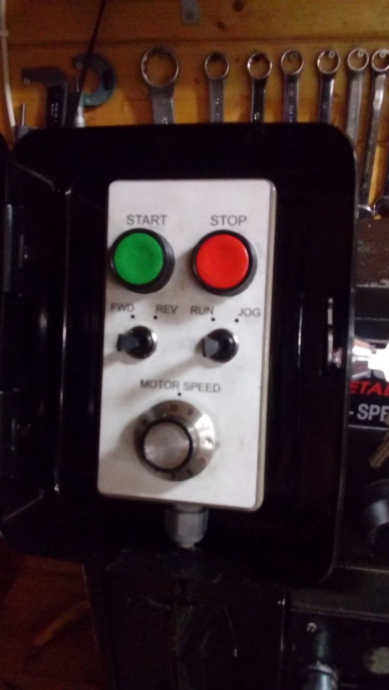
      I will show you all a picture shortly as I dismantled the pendant so I could show you, it has toggle switches for FWD/RVS and JOG/RUN, the start and stop switches are buttons and theres a vario for speed.

      The inverter can reduce it's coasting for start/stop to literally nothing so it just goes dead as soon as you hit stop, (although this can send a backwards current through the inverter due to the fact the machine will still be spinning after the power is dead) The manufacturer recommends that you use a mechanical break, as it does not have the capacity to do that electronically on this model.

      Michael W

      Edited By Michael-w on 31/03/2017 22:26:49

      Advert
      #291553
      MW
      Participant
        @mw27036

        Okay,

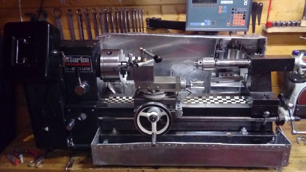
        This is the machine..

        20170331_195723.jpg

        This is the pendant front view..

        thisis.jpg

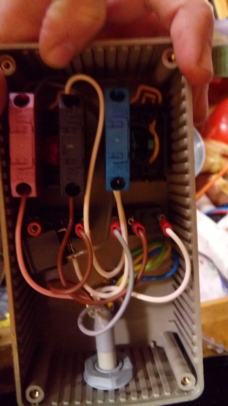
        Here is the Inside of the pendant..

        thatis.jpg

        #291555
        MW
        Participant
          @mw27036

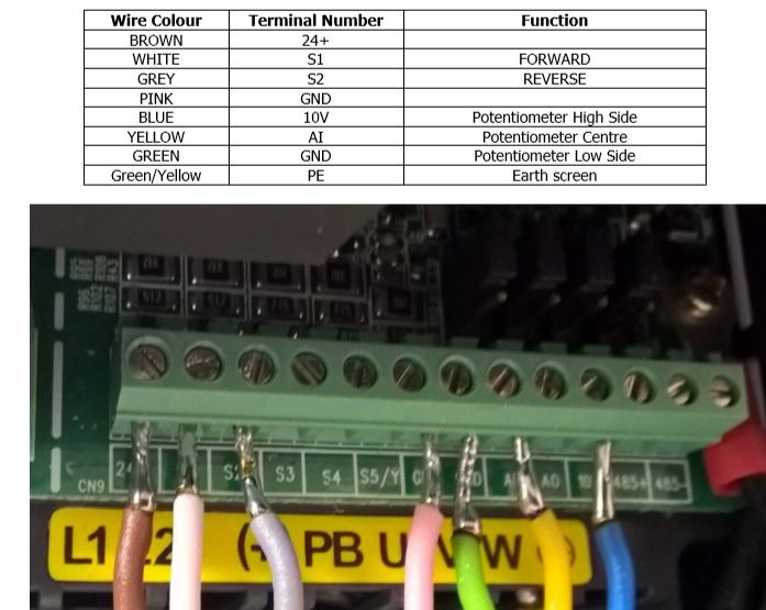
          And just for good measure i'll show the inverter view again so you don't have to keep going back to look at what it connects to…

          img2.jpg

          #291560
          MW
          Participant
            @mw27036

            So Blue, Yellow, Green (10V, AI, GND) All go to the potentiometer which is obscured by the main cable,

            White and Grey (S1, S2) are the toggle Switch for FWD/RVS. A third common cable connects this to the stop switch

            Pink (GND) connect to terminal on the STOP switch.

            This is where it gets messy. Brown (24+) goes to one side of the JOG/RUN, however the second terminal for the toggle has a relay, this connects to both start and stop, through white wires, one going to stop and two white ones going to both terminals for the START switch.

            Michael W

            #291631
            Les Jones 1
            Participant
              @lesjones1

              Hi Mitchael-w,
              I've not managed to trace out the schematic from your description and picture. I have not even worked out if it is switching the forward and reverse inputs to ground or +24 volts. (Most VFDs allow you to select this option from jumpers or a configuration setting from the buttons on the VFD) Can you measure the voltage between GND and S1 both with the motor stopped and running in the forward direction. This will let us decide if the emergency stop should be put in the +24v or the GND wire to the pendant. This is assuming you want to trust the VFD to stop the motor rather than John's method of removing the power to the VFD. I would think in a factory that his method would be the preferred way.

              Les.

              #291644
              MW
              Participant
                @mw27036
                Posted by Les Jones 1 on 01/04/2017 12:20:04:

                Hi Mitchael-w,
                I've not managed to trace out the schematic from your description and picture. I have not even worked out if it is switching the forward and reverse inputs to ground or +24 volts. (Most VFDs allow you to select this option from jumpers or a configuration setting from the buttons on the VFD) Can you measure the voltage between GND and S1 both with the motor stopped and running in the forward direction. This will let us decide if the emergency stop should be put in the +24v or the GND wire to the pendant. This is assuming you want to trust the VFD to stop the motor rather than John's method of removing the power to the VFD. I would think in a factory that his method would be the preferred way.

                Les.

                Thanks les, you have pointed me on the right track at least, i'm sure I could try making a diagram of it but maybe I already know now which two connections(brown/white) concern the running of the motor, and logically placing a normally closed switch between it would provide a means of interrupting it. I'm going to stake a bet on that a switch between +24V and the fwd/rvs switch would do exactly that, it isn't a large burden to repair the connection should it prove unsuccessful and the GND could be tried.

                The relay has complicated the situation by scrambling the connections between the START, STOP and jog/run toggle switch, I believe this is because when you switch from running to jog mode the pendant is designed to change how the stop function works. In fact the only thing with straightforward connections is the rheostat!

                I'm definitely in agreement that the most straight forward option would be between the live wire of the input and the inverter, which would mean the inverter would switch off. However, we would probably need more than a garden variety emergency stop(like a heavy duty, metal clad switch) to handle a large current passing through it and the housing/switch construction would also need to be ground.

                Michael W


                Edited By Michael-w on 01/04/2017 14:11:29

                #291652
                John Rudd
                Participant
                  @johnrudd16576

                  I suspect your pendant may be wired like this or a scheme similar to it……

                  The connections are made to correspond to the those of a Teco E2 series, yours may be different but the functionality will be the same….The speed pot value may be different as also the 12volt terminal. yours may be 24v dc.

                  The other thing to note is whether your inverter is set for active low inputs or active high…( otherwise known as PNP or NPN inputs, on the Teco drives, this is switch selectable)image.jpeg

                  #291659
                  Les Jones 1
                  Participant
                    @lesjones1

                    Hi Mitchael-w,
                    Don't connect an emergency stop switch between the brown and white wires in the VFD. It will either be in series with the brown wire +24v or in series with the pink wire GND I think it is more likely to be the +24 V

                    Hi John,
                    Thank for the Teco schematic but I think it is different to the one Michael has. The stop button appears to have two contact blocks on it.

                    Les.

                    #291662
                    John Rudd
                    Participant
                      @johnrudd16576

                      Personally,

                      I'd be inclined to cut the wire ends off and use either crimp pins or bootlace ferrules…..

                      Last thing you need is a loose wire coming adrift..

                      Hope you get sorted…

                      #291680
                      Brian Oldford
                      Participant
                        @brianoldford70365
                        Posted by Michael-w on 31/03/2017 19:48:01:

                        Ok i'll see what i can do Les, however, i don't think i ever got a circuitry diagram nor can i find one online however, i can open the thing up and see if i can make sense of the spaghetti inside, this is the best thing i could find on "what does what" for the pendant in relation to the inverter.

                        img2.jpg

                        Is that wiring real? Or is that amount of exposed conductor an April fool? I realise control signals are low voltage but it look 'orrible and is an invite to future problems.


                        Edited By Brian Oldford on 01/04/2017 17:29:48

                        #291690
                        Les Jones 1
                        Participant
                          @lesjones1

                          Hi Brian,
                          I think we now know enough to know the breaking either the +24V or the GND wire with the emergency stop button should shutdown the output of the inverter. I would of preferred Micheael to check if terminal S1 (Forward) to see if it was at +24 or zero volts when the motor was running so that we new which wire to interrupt rather than just doing it by trial and error. Many thanks for the offer to trace out the schematic of the pendant but I think we can manage without you having to do that.

                          Les.

                          #291696
                          Neil Wyatt
                          Moderator
                            @neilwyatt

                            This is how I have wired mine.

                            The problem is it's not so much HOW you wire it up,. but how you program the inverter so your wiring does what you want it to!

                            In this case X1 is programmed to do a ramped down stop when the stop switch is made and X3 to cut the power straight away when the Estop is broken so the lathe coasts to a halt (faster).

                            The box at the right is either a milliammeter or voltmeter (can't remember which), the LED is just a power LED parasitising about 10mA from the pot.


                            To confuse further if I had a braking resistor I could swap the roles of the two switches so the stop switch cuts the power to coast to a halt and the Estop does a faster stop using back-emf braking.

                            However, I happy with the e-stop causing a coast to a stop as (1) that's quite prompt on my setup and (2) that's what would happen with a traditional e-stop.

                            Edited By Neil Wyatt on 01/04/2017 18:35:54

                            #291716
                            john fletcher 1
                            Participant
                              @johnfletcher1

                              In industry the emergency stops interrupts the mains supply via a contactor, not to be confused by loco stop. I have three inverters each controlled by a 240 volt 20 amp double pole relay, by pressing the emergency stop, all the power to inverter is disconnected, it also give No Volt release, and no miss understanding.Nothing at all between the inverter out put and the motors.John

                              #291722
                              SillyOldDuffer
                              Moderator
                                @sillyoldduffer

                                Beware, this is straight from my armchair!

                                Picking up on Neil's point "The problem is it's not so much HOW you wire it up,. but how you program the inverter so your wiring does what you want it to!".

                                I found the manual for Michael's inverter at <LINK>. Starting on page 34 it describes how to allocate a function to any of the switch terminals. This is done from the keypad by navigating a nested menu. There are 34 functions listed in the P05-Group that can be allocated to a switch.

                                Michael's picture shows that S3, S4 and S5 are unused. Therefore one of them could be wired to a switch and allocated to a stop function.

                                There are a few possibilities:

                                • 6 – Coast to stop
                                • 8 – Operation pause
                                • 26 – Traverse pause (stop at the current frequency)
                                • 34 – DC Brake

                                I don't understand what 8 and 26 are, but 6 and 34 look good.

                                My lathes VFD came pre-configured so I haven't touched the keypad myself. It doesn't look difficult to program the inverter once the manual is understood but then I thought the same about sex.

                                Cheers,

                                Dave

                                #291728
                                Bob Jepp
                                Participant
                                  @bobjepp

                                  The original posts regarding the starting and stopping of an electric motor on machinery – the machine will need the following :

                                  1. A disconnection device which will default to OFF should the power fail and,

                                  2. An overload detection device to switch off the motor in case of overloading,

                                  The terms used in the previous posts should be understood as follows :

                                  DOL :

                                  The terms DOL ( Direct On Line ) refers to a device which starts the motor directly from the supply – i.e. no other device controlling the motor current.

                                  NVR :

                                  No Volt Release refers to the function whereupon the starting device will automatically drop out should the power supply fail and will remain off until the start control is re-actuated.

                                  Normally, the disconnection device relies on an electromagnet to hold in a ( or several ) switch contact(s). The electromagnet is powered from the supply via a Start push button and is held in by a closing contact of the device together with a Stop push button.

                                  These devices may be found at a number of our suppliers, I personally have used some devices from Axminster ( just because they are the most conveniently located supplier – no other reasoning ) which incorporate the Start and Stop push buttons as well as the NVR. Regarding overload protection, a correctly rated fuse is the absolute minimum requirement although various other specialist motor overload devices are also available.

                                  Make sure that you do a risk assessment ( sorry – had to mention that ). You should consider the following and, in addition, any other pertinent points :

                                  1. Conveniently located start and stop button ?

                                  2. Once started, does the motor turn off AND STAY OFF if the supply is switched off and then on again ( NVR ) ?

                                  3. Do you require any additional Stop devices such as guard safety limit switches of extra Stop buttons ( must be normally closed contacts in series with the Stop push button?

                                  4. Have you incorporated an overload device which will shut down the NVR when it trips ?

                                  OK, sorry about that, on to the inverter controlled motor – Lets be clear about the meaning of an Emergency Stop. Emergency Stops must safely remove energy from driven devices. With inverters, there are several ways to do this :

                                  1. A disconnection device between the power source and the inverter,

                                  2. A disconnection device between the inverter and the motor,

                                  3. An inverter with built in safety outputs,

                                  Considering each option :

                                  1. A disconnection device ( NVR ) between the supply and the inverter is generally considered to be the safe option, but, the inverter will retain some charge at power down allowing the motor to continue running for a short time. Your risk assessment will tell you whether this is acceptable – industrially this method is going out of favour,

                                  2. A disconnection device between the inverter and the motor potentially has the capability to remove the load from the inverter whilst running at 'full whack' causing a catastrophic failure of the inverter. This is obviously not good although some inverters are capable of withstanding this and others may or may not have a special input to feed back the status of the disconnect device to shut down the inverter when the NVR switches off,

                                  3. Inverters with safety outputs are becoming increasingly the way to go. They incorporate two dedicated inputs whose job it is to shut down the outputs of the inverters in a guaranteed safe manner. Inverters incorporating these safe outputs need to be specifically selected,

                                  So, the difference between Stop and Emergency Stop is that Emergency Stop must remove power from the motor in an approved safe fashion – again ( sorry ) your risk assessment should ask the question "When is Stop safe enough ?". If you are putting your hands into a lathe, maybe holding a chuck key, do you want to rely on the inverter to stop the rotation of the chuck ?

                                  Just bear in mind that all modern inverters rely upon software to drive the motor – the basic principle of safe design is that software can fail and Murphy's Law says that it will always fail in the most un-safe way possible.

                                  Bob


                                  Edited By Bob Jepp on 01/04/2017 22:56:02

                                  #291738
                                  Emgee
                                  Participant
                                    @emgee

                                    Hi Bob

                                    Think most of your posting has already been stated but it's good to have confirmation.

                                    Emgee

                                    #291768
                                    SillyOldDuffer
                                    Moderator
                                      @sillyoldduffer
                                      Posted by Bob Jepp on 01/04/2017 22:51:16:

                                      So, the difference between Stop and Emergency Stop is that Emergency Stop must remove power from the motor in an approved safe fashion – again ( sorry ) your risk assessment should ask the question "When is Stop safe enough ?". If you are putting your hands into a lathe, maybe holding a chuck key, do you want to rely on the inverter to stop the rotation of the chuck ?

                                      Just bear in mind that all modern inverters rely upon software to drive the motor – the basic principle of safe design is that software can fail and Murphy's Law says that it will always fail in the most un-safe way possible.

                                      Bob

                                      Edited By Bob Jepp on 01/04/2017 22:56:02

                                      Assuming that Michael doesn't want to change his inverter, I'd suggest using the built in brake function would be the best approach in the circumstances:

                                      • He has no form of emergency stop at the moment.
                                      • Assuming the motor to be driving the lathe at speed when the emergency occurs:
                                        • Disconnecting the single phase mains will cause the motor to coast to a stop. While coasting it is still dangerous.
                                        • Disconnecting the 3-phase output is somewhat complicated, risks damaging the inverter, and the motor will coast to a stop. While coasting it is still dangerous.
                                        • Using an inverter function to apply a braked stop is the quickest way to stop the lathe. If the brake part fails, the power is still disconnected and we are no worse off in that the lathe will coast to a stop,

                                      Bob's comment about software failing is very true. "Failsafe systems fail by failing to fail safely". However, is there any evidence that Inverters suddenly go mad and refuse to stop? Although affordable inverters are a recent innovation, the technology has been around for about 40 years and works well. So Michael's risk assessment might legitimately conclude "In the event of a unlikely 'hand in the works' emergency, the fastest way of stopping is to use the inverter and risk of my inverter failing to stop and brake is low.

                                      Bob has highlighted one of the main advantages of doing a Risk Assessment, which is peer review. He put his thoughts in writing and we were able to review them. I have put my thoughts in writing too. I'm absolutely not saying Bob is wrong, rather I'm suggesting an alternative for consideraton. Michael and others now have the opportunity to spot logical flaws, mistakes and misunderstandings etc. That should lead to a more balanced risk assessment, perhaps inspiring Michael to change his inverter.

                                      One good thing for me is that I've realised that I don't know how the emergency stop on my lathe is implemented. I assumed hitting the big red button would do the very best thing; now I'm off to study the wiring diagram.

                                      Dave

                                      #291786
                                      Bob Jepp
                                      Participant
                                        @bobjepp

                                        Thanks Dave, now I'll have to let you into a secret – I have risk assessed my lathe and reverse engineered the circuit diagram only to find out that the 'so called Emergency Stop' in no way conforms to the legislation.

                                        The stop side of the inverter, which included the guard safety switches, are open contacts which close when the Emergency Stop is pressed – a serious no-no in control systems. Needless to say, it's on the list of jobs to address – but I haven't as yet come up with a solution as the inverter is Chinese and I'm not understanding their manual too well !

                                        Just a little explanation of the no-no :

                                        Safety contacts should be normally closed and open when the device is actuated – Why ? – well several reasons :

                                        • Firstly, should the wire fall off, the circuit will shut down,
                                        • Secondly, should the switch fall apart, failing in the open mode, the circuit will also shut down and
                                        • Thirdly, should the switch contacts weld closed, the actuation of the mechanical part of the switch will forcibly disconnect the circuit ( albeit leaving the device permanently damaged, but better than an injury – eh ).

                                        Using standard European Approved Emergency Stop push buttons will provide these safeguards, but, limit switches for guard interlocks are not so easy to specify correctly as the safe operation of the switch depends upon the correct mechanical application of the switch as well as the electrical aspects. Just take a moment to think about a limit switch applied to a safety guard – on my milling machine, there is a belt guard safety switch which is depressed when the belt guard is closed, relying on the spring inside the switch to operate the mechanism when the guard is opened – what happens if the spring fails or the switch jams ?

                                        Bob

                                        #291804
                                        SillyOldDuffer
                                        Moderator
                                          @sillyoldduffer

                                          Hi Bob,

                                          So far so good with my WM280. The emergency off and safety interlocks are all in series and they are Normally Closed types.

                                          They break a live mains connection to the Contactor which is as far as I've got. After that I'm not sure if the contactor disconnects the Inverters power input directly , or if it works a control input. (The inverter stays powered up even if the emergency stop is pressed.)

                                          All would become clear if I knew what the abbreviations meant. Guess who can't find the Inverter Manual even though I clearly remember putting it in a safe place. No idea which one though.

                                          Dave

                                          #291805
                                          Harry Wilkes
                                          Participant
                                            @harrywilkes58467
                                            Posted by Brian Oldford on 01/04/2017 17:29:21:

                                            Posted by Michael-w on 31/03/2017 19:48:01:

                                            Ok i'll see what i can do Les, however, i don't think i ever got a circuitry diagram nor can i find one online however, i can open the thing up and see if i can make sense of the spaghetti inside, this is the best thing i could find on "what does what" for the pendant in relation to the inverter.

                                            img2.jpg

                                            Is that wiring real? Or is that amount of exposed conductor an April fool? I realise control signals are low voltage but it look 'orrible and is an invite to future problems.

                                            Edited By Brian Oldford on 01/04/2017 17:29:48

                                            Brian was just thinking the same thought ref messy wiring also personally I do not like soldered ends after many years of fault finding I wouldn't mind a £1 for every bad connection I've found due to soldered or crimp terminations on low volt control wiring.

                                            H

                                            #291806
                                            MW
                                            Participant
                                              @mw27036
                                              Posted by Harry Wilkes on 02/04/2017 14:32:42:

                                              Posted by Brian Oldford on 01/04/2017 17:29:21:

                                              Posted by Michael-w on 31/03/2017 19:48:01:

                                              Ok i'll see what i can do Les, however, i don't think i ever got a circuitry diagram nor can i find one online however, i can open the thing up and see if i can make sense of the spaghetti inside, this is the best thing i could find on "what does what" for the pendant in relation to the inverter.


                                              Is that wiring real? Or is that amount of exposed conductor an April fool? I realise control signals are low voltage but it look 'orrible and is an invite to future problems.


                                              Edited By Brian Oldford on 01/04/2017 17:29:48

                                              Brian was just thinking the same thought ref messy wiring also personally I do not like soldered ends after many years of fault finding I wouldn't mind a £1 for every bad connection I've found due to soldered or crimp terminations on low volt control wiring.

                                              H


                                              Before! we drift into the world of pendantry may I remind you this isn't my image, this is transwave converters or power capacitors' image, not mine, yes mine are similar to this, no, nothing has gone wrong because of it.

                                              They manufacture these units commercially, and have done so for a very long time, if they can't competently do it, then maybe you should tell them, because it isn't bothering me or my inverter(s).

                                              In fact, I don't think any of those connections are clamped in the holder, they are simply presenting them to show you where they go.

                                              Michael W

                                              Edited By Michael-w on 02/04/2017 14:53:40

                                              #291810
                                              Neil Wyatt
                                              Moderator
                                                @neilwyatt
                                                Posted by Bob Jepp on 02/04/2017 12:39:17:

                                                The stop side of the inverter, which included the guard safety switches, are open contacts which close when the Emergency Stop is pressed – a serious no-no in control systems. Needless to say, it's on the list of jobs to address – but I haven't as yet come up with a solution as the inverter is Chinese and I'm not understanding their manual too well !

                                                Please see the link I posted for a way to do this.

                                                The other is to fit an E-stop between the supply and the inverter (you need a specially designed inverter if you want to fit one between it and the motor).

                                                If no braking resistor is fitted to the VFD, coast to stop should be OK as this is the normal situation with non-VFD machines unless they are big enough to need a brake in which case a mechanical one is fitted (although separate to the estop).

                                                #291816
                                                John Rudd
                                                Participant
                                                  @johnrudd16576
                                                  Posted by Neil Wyatt on 02/04/2017 15:26:44:

                                                  If no braking resistor is fitted to the VFD, coast to stop should be OK as this is the normal situation with non-VFD machines unless they are big enough to need a brake in which case a mechanical one is fitted (although separate to the estop).

                                                  There is the DC injection option, on operating an E stop, DC is injected to the motor bring it to a rather abrupt stop…

                                                  #291841
                                                  MW
                                                  Participant
                                                    @mw27036

                                                    Ok, there has been a lot of responses to this, in one case i'm glad but in another sense, my apologies to the OP for diverting the topic of conversation to this, I just didn't think it would generate this much talk at the time.

                                                    I'm thankful to all the sensible posters who have come up with what needs to be considered with regards to the inverter, I feel i'm left with a couple of options.

                                                    1. Provide an emergency stop directly to the source of the power, namedly an emergency "type" stop to bridge the single phase live wire from the wall socket to the inverter,

                                                    providing it does what is intended, it shall provide an almost guaranteed cut-off of power, that much we can be sure of, However, what is not certain, is if the inverter will actually shut off instantly, it actually takes 3-4 seconds to respond to the wall socket being switched off, this would not suffice as an emergency stop if that is the case.

                                                    2. Use either the existing connections between GND/24V on the controls, OR to use the free ports to program/remap a new function that interrupts the motor with no coasting time, I have used this inverter control before to setup new frequency from 50hz to 60hz parameters so I am fairly familiar with the jargon and how it's laid out.

                                                    I am aware that if I am successful it may not come under the technical definition of an "emergency" stop, but i'm not perfect, the worlds not perfect, and no matter how stupid anyone thinks I am, I did at least try to pre-empt some kind of risk here, as well as an opportunity to learn more about the system, this might lead me to knowing how to rig some L.E.D's in parallel to the system to have functioning lights.

                                                    For the ambiguity that I still have in my mind with regards to what route I shall take, I have made sure that the red button twist switch I have chosen, will be able to sustain a thermal current load (I-th) of 10A and 660V, well within the remit of a 7A maximum 2.2KW inverter.

                                                    I can't really do much until then but I will trawl through the manual to see what I can gather as to whether a programmable function is doable.

                                                    Thankyou,

                                                    Michael W

                                                    Edited By Michael-w on 02/04/2017 18:37:04

                                                    #291878
                                                    Neil Wyatt
                                                    Moderator
                                                      @neilwyatt
                                                      Posted by John Rudd on 02/04/2017 15:54:48:

                                                      Posted by Neil Wyatt on 02/04/2017 15:26:44:

                                                      If no braking resistor is fitted to the VFD, coast to stop should be OK as this is the normal situation with non-VFD machines unless they are big enough to need a brake in which case a mechanical one is fitted (although separate to the estop).

                                                      There is the DC injection option, on operating an E stop, DC is injected to the motor bring it to a rather abrupt stop…

                                                      The problem is that you can't have both a gentle ramped down stop AND a braked stop programmed at the same time.

                                                    Viewing 25 posts - 26 through 50 (of 50 total)
                                                    • Please log in to reply to this topic. Registering is free and easy using the links on the menu at the top of this page.

                                                    Advert

                                                    Latest Replies

                                                    Viewing 25 topics - 1 through 25 (of 25 total)
                                                    Viewing 25 topics - 1 through 25 (of 25 total)

                                                    View full reply list.

                                                    Advert

                                                    Newsletter Sign-up