Making form relived cutters

Advert

Making form relived cutters

Viewing 16 posts - 1 through 16 (of 16 total)
  • Author
    Posts
  • #802830
    Dave S
    Participant
      @daves59043

      I want to make some gears shortly, so I thought I’d try and make the cutter using my fancy new CNC 🙂

      This is a proof of concept, still got some bugs to work out, but thought I’d share incase it inspires anyone.

      Backstory – About 6 years ago I started a clock (no rush…). and for that I made a rack form gear cutter. There is a thread over on the Homeshop Machinist BBS (https://bbs.homeshopmachinist.net/forum/general/81473-making-a-gear)

      Some of the people over there where quite upset I didn’t have an relief on my cutter.

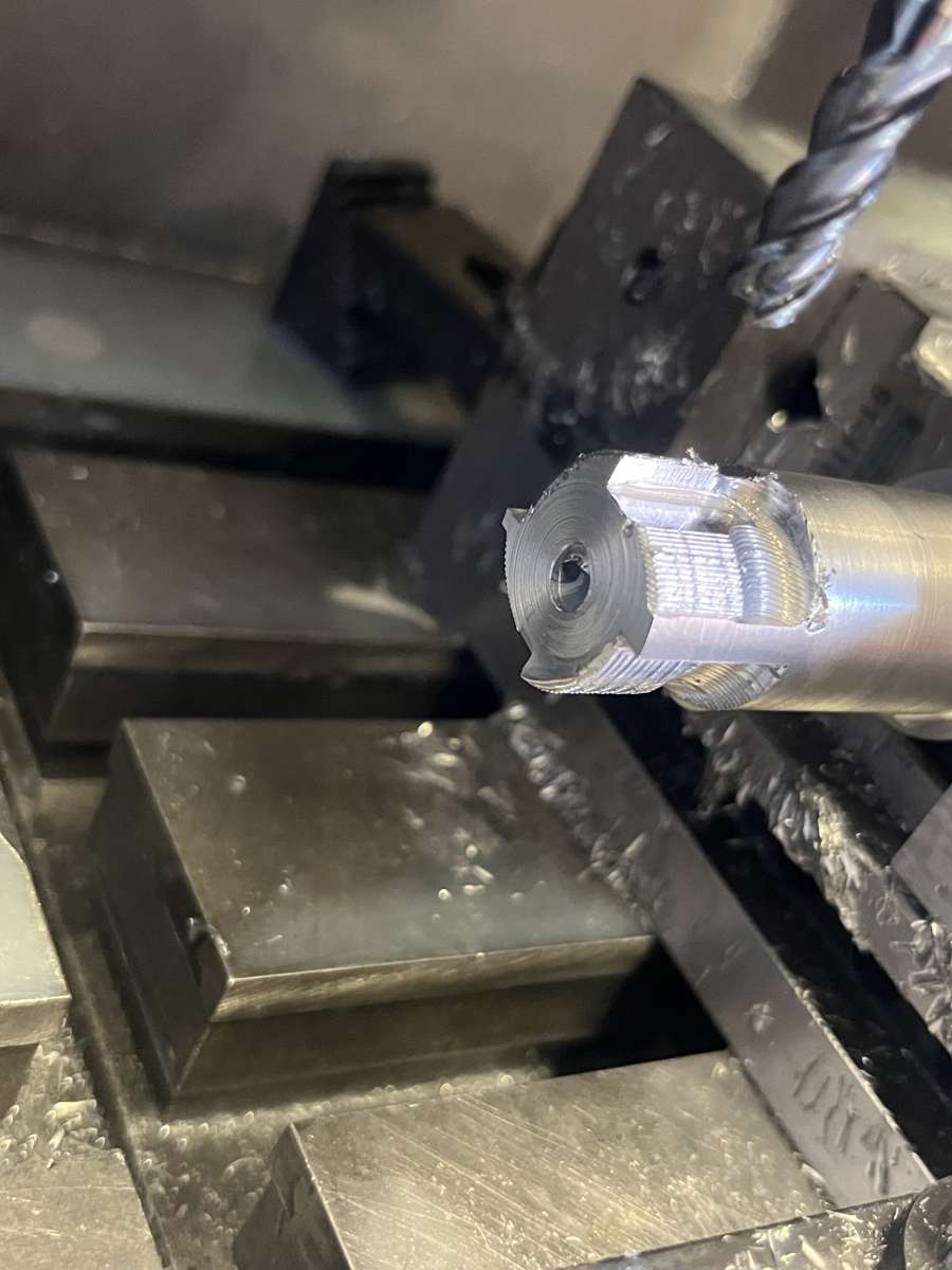
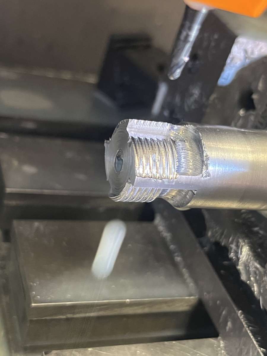
      So here is a 4 tooth, rack form, relieved cutter I knocked up in Fusion360:

      fusionmodel

      I didn’t model the shaft as the stock to make if from will just be that.

      IMG_7085IMG_7087

      Made it from some cold rolled I had lying around – horrible to machine, but for a proof of concept adequate.

      Ive only run 2 of the 4 index positions – hence the part formed teeth.

      Need to not snap the end off the V cutter for the finishing paths, but otherwise looks very plausible.

      Will do a few more tweaks then knock one out of silver steel, hardened it an give it a go.

      Dave

      Advert
      #802864
      Huub
      Participant
        @huub

        Did you use a 20° V-bit to cut the grooves and will the tool be used for gear hobbing?

        #802877
        Dave S
        Participant
          @daves59043

          Yes.
          Roughed out with a 6mm endmill

          IMG_7082

          Then smoothed with a 3mm ball nose

          IMG_7083

          Which starts the top of the grooves. Then a 20 degree V bit for finishing. Thats the one which pinged off the end almost as soon as it started 🙁

          Might need to use a 1mm ball nose to remove more of the groove first, and certainly need to practice making v cutters.

          Not exactly hobbing, more Rotary Sunderland Gear Planing.(which is sort of 0 degree lead hobbing if you squint)

          Dave

          #802887
          SillyOldDuffer
          Moderator
            @sillyoldduffer

            Excellent!  And a good example of CNC cutting a path that’s difficult to create manually.

            Pedant alert, Dave’s cutter doesn’ hob gears!  It’s a gear shaper, due I think to a British engineer name of Sanderson, who realised that round involute gears can be generated from a straight rack form.   Unlike a hob, bits of more than one tooth are cut by the rack at the same time, the resulting curves being generated ever more accurately by rotating the blank, one tooth at a time.

            rack1

            Advantage is gears can be cut without hob, and can be home-made!   Disadvantage is shaping is slower than hobbing.

            At one time I made about 40 Meccano gears with a DIY rack cutter, crude compared to Dave’s.  Worked OK on Brass, but tended to smear Aluminium and mild-steel, I guess because the relief was too simple.   Neil Wyatt used the same method on his Jovilabe project; his cutter was much better made than mine!

            Dave


            #802891
            duncan webster 1
            Participant
              @duncanwebster1

              I think with a Sunderland machine the cutter movea sideways slowly and the gear turns in sympathy. Eventually the cutter runs off the end, and the gear is rotated by a numbet of teeth to start again. Invented by a Yorkshireman,  so must be good. There is a mesmerising video on the lathes.co site

              If you had enough patience and a shaper you could do it with a single point cutter.

              #802902
              Julie Ann
              Participant
                @julieann

                This is an interesting thread; I have a few comments.

                If I understand correctly the cutter rotates, but is not a hob. Instead a number of passes are made and between each pass the gear blank is rotated and moved linearly. Exactly the same as a Sunderland gear planer as described by Duncan. On a Sunderland planer the cutter doesn’t need to rotate and is just a flat section of a rack with simple relief akin to that used on lathe tools.

                Having just read the linked thread in OP it seems I have correctly understood the process.

                Given that the OP has a CNC mill there are a couple of simpler alternatives. First, just make a form relieved cutter to cut a single tooth in one one as per commercial gear cutters. This cutter was made on a CNC mill, from gauge plate, for cutting a spline complete with form relief. Making one for a gear would be simple:

                2013_08260080

                Second, each gear could be designed in CAD, with the correct tooth form, and cut directly on the CNC mill; no need to make a cutter. The sequence is CAD model:

                Pinion 21 Teeth 10DP 20PA

                CNC milling:

                Pinion 21 teeth 20PA

                Finished gear set:

                Internal Gear and Pinion

                For very small gears, or gears too big for my CNC mill, using commercial or homemade cutters is still the best choice. Otherwise I tend to cut gears directly on the CNC mill and cut out the middle man, so to speak.

                Julie

                #802904
                Huub
                Participant
                  @huub

                  Second, each gear could be designed in CAD, with the correct tooth form, and cut directly on the CNC mill

                  Cutting gears on the CNC is “limited” (gear thickness) by the end mill cutting edge length. For coarse gears it is an easy option.

                  Gears can be cut using a slitting saw, manual mill and manual rotary table. I have never tried this but if the slow process is not a problem, it could be a promising way for coarse gears especially on a 4 Axis CNC.

                  I have made gears and gear cutter using the manual mill and cnc lathe. I am working on making an end mill style gear cutter on the CNC router, nothing more than the automated version of my manual procedure.

                  I only made 3D printed internal gears, never tried milling or broaching them.

                  #802912
                  Julie Ann
                  Participant
                    @julieann
                    On Huub Said:

                    Cutting gears on the CNC is “limited” (gear thickness) by the end mill cutting edge length.

                    I don’t understand that; I’ve never been limited by flute length?

                    Since the involute form is curved, the complete tooth flank isn’t cut in one pass. The only requirement is that cutter can reach the bottom of the tooth gap while still clearing the crest. That is not the same thing as flute length. I use standard ballnose cutters. The main limitation on cutter size is set by the root radius of the gear.

                    The gear shown above was machined in two stages. First, a roughing operation going round the gear multiple times, stepping down a fixed amount at each pass to remove the bulk of the material:

                    Pinion - Rough Machining

                    Second, a finish pass which is profiling, going round the gear once:

                    Pinion - Finish Machining

                    I 3D printed the internal gear set to check that the profiles were correct, and hence that meshing was smooth, before cutting metal:

                    Internal Gears

                    Julie

                    #802916
                    Huub
                    Participant
                      @huub

                      I don’t understand that; I’ve never been limited by flute length?

                      Julie,

                      You cut the gears radial on the CNC and need a rotary table. That explains why your end mills are long enough for the job.

                      I would cut gears axial with the gear blank mounted flat on the bed so I don’t need a rotary table. The thin tooth bottom (crest) width requires thin end mills that are to short to cut the full depth (gear thickness).

                      A module 1, 20 tooth gear has a crest width of about 1 mm. In general a 1 mm end mill has a flute length of 2.5 mm. That would limit my method, to cut a gear on the CNC router, to a gear thickness of 2.5 mm or less.

                      #802917
                      JasonB
                      Moderator
                        @jasonb

                        The OP’s cutter means he only needs to make one cutter and it will cut any number of teeth. Making a single cutter like the spline one would need a new cutter for each tooth count or a set like off the shelf involute cutters

                        His gear cutter looks like it will suit quite a small DP or MOD size which would need a very small diameter cutter to get to the root of the teeth which means slow shallow cuts where as the rack cutter will do them in less time. 48DP I think.


                        Also I don’t think he has a 4th axis so would be limited to cutting with the gear laid flat and then dia of cutter needs to fit the root  (0.5mm dia) and you then also become limited but flute length of the small dia cutters. With the rack cutter he just needs to index the number of teeth. CNC can be set to do a basic feed and return then just index to the next tooth and repeat.

                        #802920
                        Dave S
                        Participant
                          @daves59043

                          The cutters are going to be for watch sized gears, so the direct with an end mill approach – either flat or radially – is not viable. A thin slitting saw might work, but they are also somewhat fragile.

                          This proof of concept has 0.35mm root, that’s one of the reasons I ended up snapping the tip off the 20 degree finishing cutter – it was 0.18mm across (I was aiming for 0.2 but missed…).

                          My CNC was deliberately build with 150mm of work area, large enough without being too big. I don’t have a 4th axis for it (yet – maybe in the future) so the gear cutting will be taking place on my TOS FNK25.

                          Jason’s nailed the lazy engineer approach – rack form cutters can be used to cut any number, unlike the approximation used for form cutters. I need to revise (its been a while) but I think that’s also true for Cycloid rack form.

                          The other useful thing from this is an oddball form cutter (beveled T slot for instance) can be made with relief, which might be useful for a lot of other jobs (threadmilling seems like a possibility)

                          Duncans right that the gear rotates as the rack planes it in a Sunderland machine. This is sort of the equivalent to the lead angle on a hob. fortunately those 2 movements don’t have to be synchronised – its possible to cut the whole gear using normal dividing, then rotate the gear by a fraction of a tooth, move the cutter up the equivalent amount and then go round again – not as fast, but the same outcome.

                          Dave


                          #802922
                          JasonB
                          Moderator
                            @jasonb

                            I posted these pictures a while ago that show how the rack form cutter machines several teeth at each index and gives a faceted face to the tooth. reposition cutter and offset the index to get less facets.

                            #802942
                            Julie Ann
                            Participant
                              @julieann

                              Huub: Thanks, I understand now.

                              DaveS: All I can say is good luck. While rack cutters, and hobs, can cut any number of teeth they leave an approximation as the tooth form is a series of facets. An individual involute cutter is exact for the lowest tooth count in the range. I doubt I could use the rotate and shift method. I’d get bored long before I finished and would end up making a mistake. With CNC you can set it running and then go and do something more interesting.

                              While I have made lots of gear types, with involute tooth forms, on both manual and CNC mills, I’ve never made a gear using the cycloidal form. But looking at the geometry I don’t think they can be made using the rotate and shift method. To an extent there is no need, as for wheels a single cutter will cut all tooth counts. Pinions (less than 20 teeth) are a different matter and a seperate cutter is needed for each tooth count.

                              Julie

                              #802955
                              JasonB
                              Moderator
                                @jasonb

                                I suppose once you have prooved the concept of cutting form relief there is nothing to stop you making cycloidal form cutters using the same method. And it could be done with a single set of teeth just as easily as multiple teeth, the multi teeth would just act as roughing cutters either side of the central one that cuts the full form so spreading wear over your homemade carbon steel cutters (provided it works with a rack). Just make one for the wheels and as many as you need for the lower tooth count pinion cutters. Got to be cheaper than £80 a pop for commercial cutters.

                                The advantage of a single cutter rather than rack is the form relief can be done with the cutter held flat to cut one side at a time and even with a smallish overall gear cutter dia the toolused to cut it could be a reasonable size say 2-3mm ball nose as you don’t need a tight internal corner.

                                Julie, what would be your method for making the small gears that the OP wants so that he could walk away?

                                #802959
                                John Haine
                                Participant
                                  @johnhaine32865

                                  I’m fairly sure that so-called cycloidal teeth can’t be hobbed in the same way as involute with a single rack form cutter for a wide range of counts. I think a hob is needed per tooth count. They can certainly be form relieved.

                                  #803001
                                  Julie Ann
                                  Participant
                                    @julieann
                                    On JasonB Said:

                                    Julie, what would be your method for making the small gears that the OP wants so that he could walk away?

                                    The comment on walking away leaving the CNC mill running was in contrast to the method of rotate and step.

                                    As far as watch gears go (assuming they are cycloidal) I agee with JohnH; they cannot be made by hobbing or the rotate and shift method.

                                    There are two approaches that I’d try. First, endmills are available down to 0.1mm diameter so it should, in theory, be possible to mill the teeth with the blank flat on a CNC mill. Watch gears are usually fairly thin so flute depth shouldn’t be an issue. An acceptable form of the cycloidal tooth form has a semi circle at the bottom of the tooth rather than a flat. On my CNC mill thus far I’ve used cutters down to 0.5mm diameter on both steel and brass with only two breakages. The breakage problem was solved by using a better quality cutter.

                                    Second, I’d make a suitably formed flycutter, or rotary cutter, and cut the gear by indexing round one tooth at a time. If nothing else it would be an excuse to get my Pultra lathe with toolpost milling spindle and headstock dividing head, up and running:

                                    2016_04070004

                                    Julie

                                    PS: Out of idle curiosity I’ve ordered a book on cutting clock/watch wheels and pinions so I can learn more.

                                  Viewing 16 posts - 1 through 16 (of 16 total)
                                  • Please log in to reply to this topic. Registering is free and easy using the links on the menu at the top of this page.

                                  Advert

                                  Latest Replies

                                  Viewing 25 topics - 1 through 25 (of 25 total)
                                  Viewing 25 topics - 1 through 25 (of 25 total)

                                  View full reply list.

                                  Advert

                                  Newsletter Sign-up