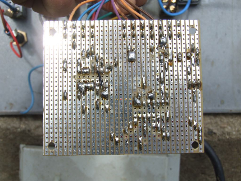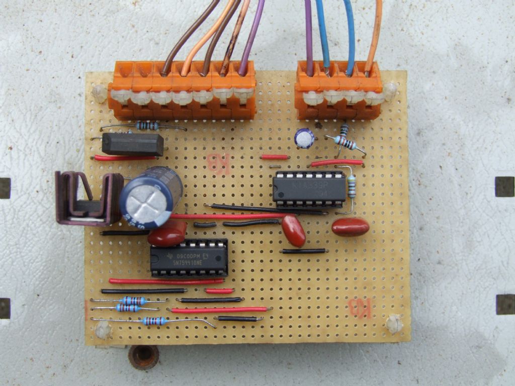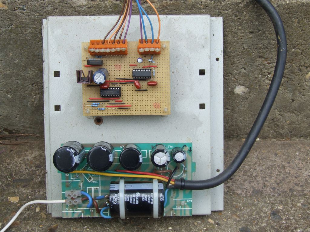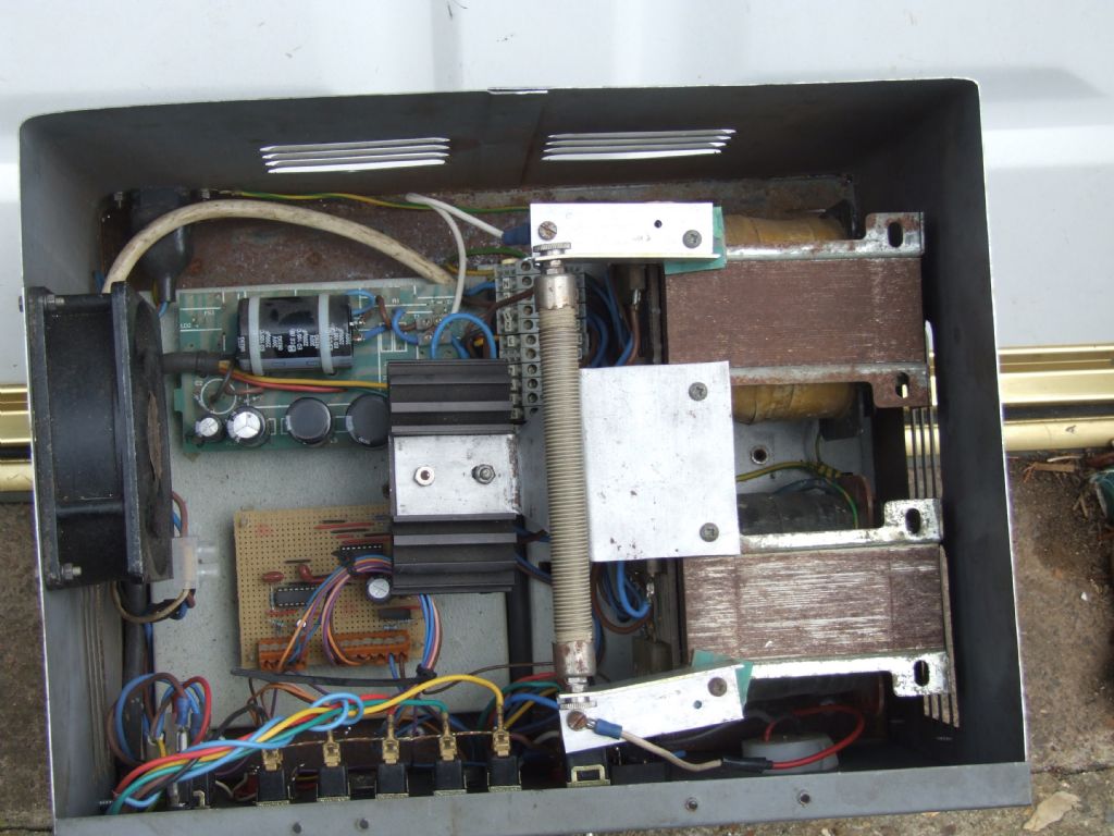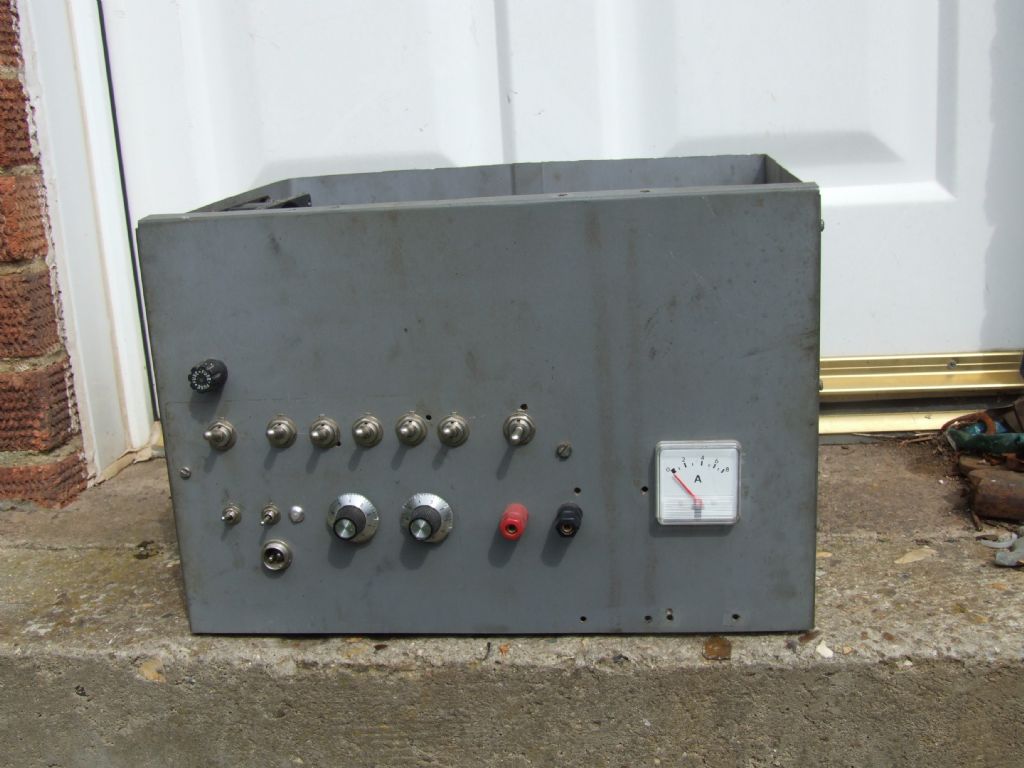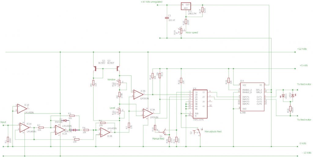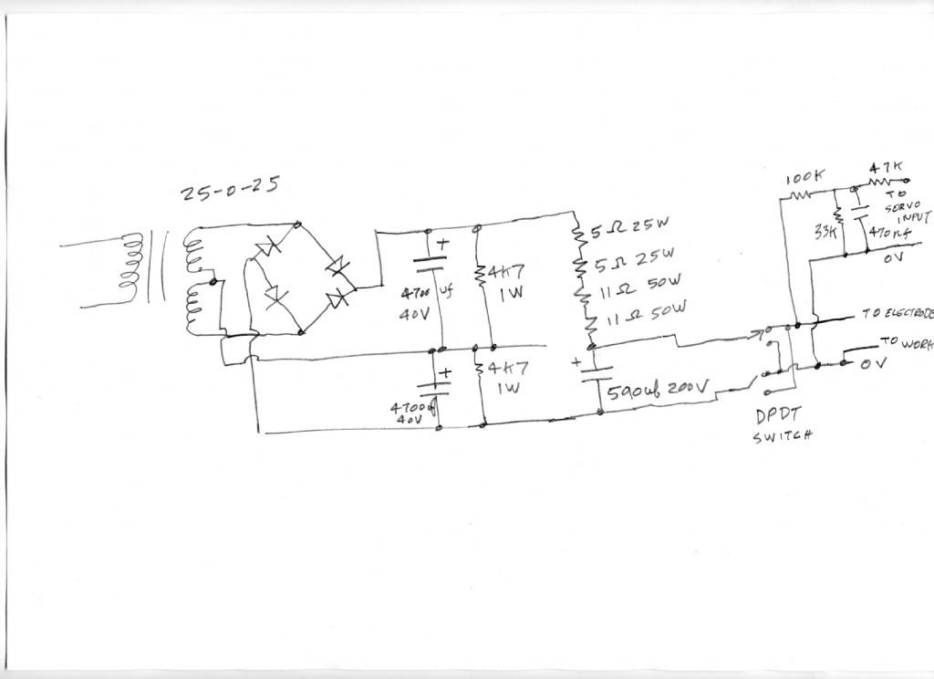


 I have dismantled the EDM today,it was built in 5 parts, The case, front panel with all the controls, the power supply, capacitor bank and control board. I have included some pictures of the parts.to give an idea of how it was built. The control circuit board is based on Ben F
 lemings circuit but built on strip board. The 2 ic s that were used were mounted in holders to avoid the risk of damage due to static or heat and make testing or repair simple. The front panel starting top left, mains fuze 5A, mains switch, to the right 5 switchable capacitors, & the 66V or 100V switch. Bottom left,cutting head motor switch on/off, centre off, up or down. A bicolour LED to indicate up or down movement, this is a failure & will be changed for 2 separate LEDs. Set voltage pot and voltage spread pot. Red and Black power output sockets. Lower left is the cutting head indexable socket. Whilst the ampmeter was fitted, I have not got round to fitting the Voltmeter – yet ! I Suppose you want me to draw up the strip board layout and cutouts ?
The cutting head I have yet to find, it's in one of the sheds, there is as much work in making this as the power supply and is the real key to good operation and results. One thing I found vital was to be able to obsereve the rotation of the leadscrew, this was achieved by sticking a strip of barcode round the shaft. Steady fore and back movement, but more fore indicated cutting, constant fore indicated you were through, hold motor up, job done ! Noel.
Edited By noel shelley on 09/05/2021 14:26:47
Andre ROUSSEAU.


