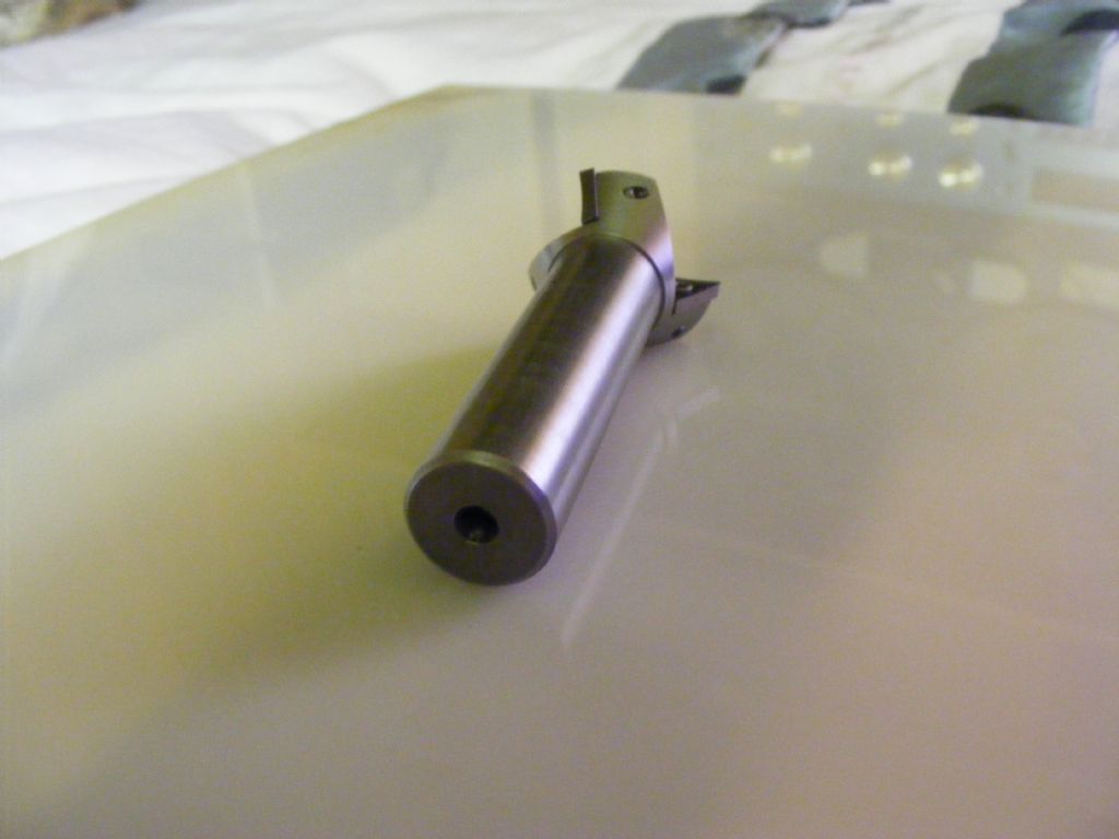
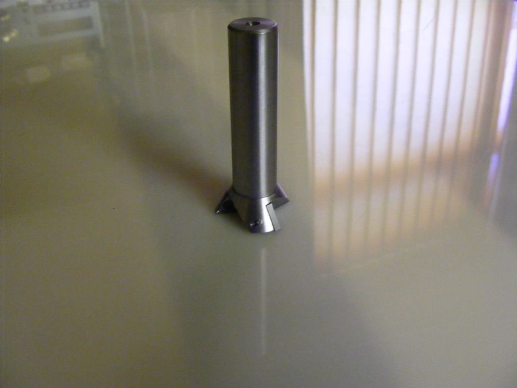
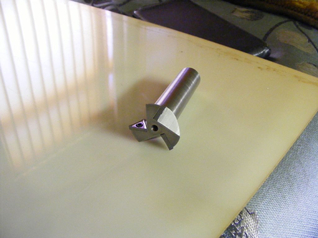
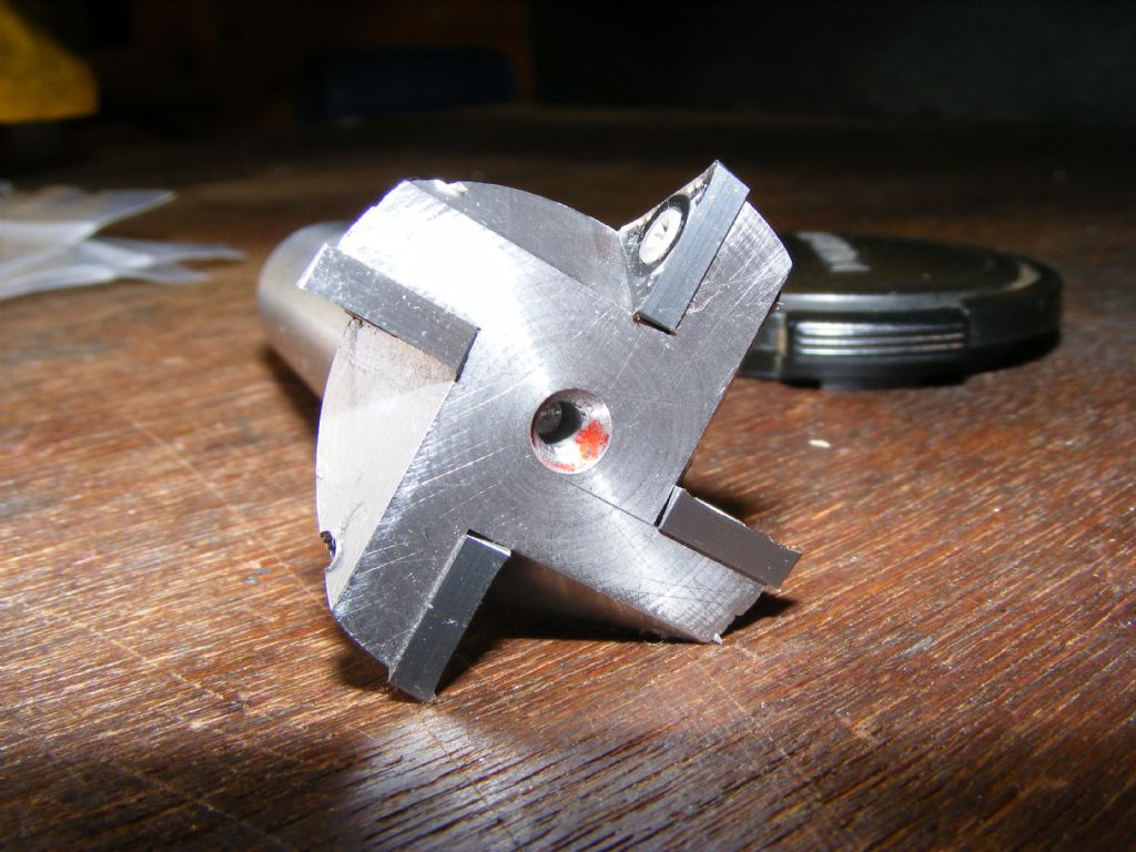
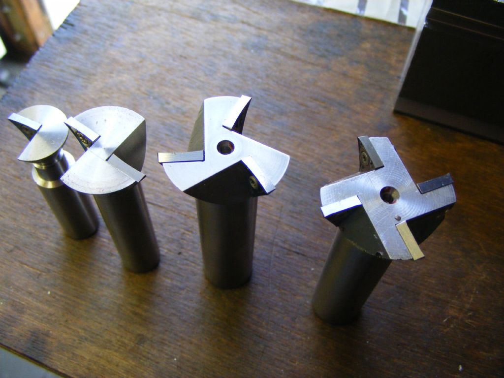
My mistake, Raymond. I'd overlooked the fact that these were positive inserts. IIRC, the presence of a screw pretty much tells you that it's a positive one. The 7 degree angle isn't easy to make out in the photos – well that's my excuse anyway.
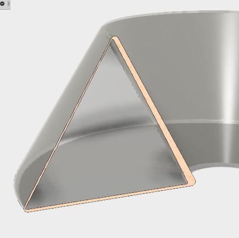
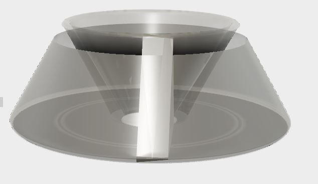
In the interests of science and to test my Fusion 360 skills, I made a 3D model of the insert and used it to produce a revolve extrude (using the front cutting face of the insert) and made a circular sweep cut (using the trailing face – they are offset by 2.38mm). The shell formed by these operations shows the clearance at the trailing edge and if this reached zero there would be burnishing. You can clearly see that there is a small gap. Fusion's measuring tool doesn't seem to offer any means of measuring the thickness but the large (outer) chamfer radius is 0.4mm for scale.

I hadn't realised how large the tool was. The length of the cutting edge is about 19mm for a "11mm" TPGT insert and there appears to be about 8mm between inserts, making the overall major diameter about 44mm(?). Fusion 360 struggles to report any useful measurement as things stand. Hopefully they will improve that aspect soon. However, playing with the position of the insert it seems that until the radial distance between the inserts goes below zero, the clearance is finite. Once you go to a single insert and start to bring the inside edge of that insert within and past the centre line, the clearance will become zero. That means you can't reduce the overall diameter below about 3.5 times the inscribed diameter (11mm here) with a TPGT insert.
This would have been easier in Solidworks, Solid Edge, Inventor etc but I thought I'd explore Fusion and also my own capability.
Hope this is vaguely interesting!
Murray
Raymond Anderson.


