Bridgeport wiring

Advert

Bridgeport wiring

Home Forums Manual machine tools Bridgeport wiring

Viewing 13 posts - 1 through 13 (of 13 total)
  • Author
    Posts
  • #135284
    Richard Clark 1
    Participant
      @richardclark1

      Hi,

      I have just purchased a 1972 Adcock and shipley bridgeport mill and I cant seem to find any wiring diagrams, to date I have found nothing on the internet, so im hoping someone on here maybe able to help.

      What I would like is the wiring diagram of the big metal enclosure box mounted on the side of the mill it has a transformer and contactors and an isolator switch.

      Hopefully someone can help on here.

      Thanks in advance

      Richard

      Advert
      #12214
      Richard Clark 1
      Participant
        @richardclark1
        #135285
        Les Jones 1
        Participant
          @lesjones1

          Hi Richard,
          I have seen several different schematics for Bridgeports so you will probably not find one to exactly match your machine. Here is a link to a manual which contains a partial schematic near the end. I have some more schematics as .jpg files which I can email to you if you PM me with an email address.

          Les.

          #135449
          Richard Clark 1
          Participant
            @richardclark1

            Hi Les,

            Thanks for the link to manual I have sent you my email address.

            ps dont know if you or anyone else have a diagram for the erskine power feed pcbs as any info would be great.

            Regards

            Richard..

            #135453
            Les Jones 1
            Participant
              @lesjones1

              Hi Richard,
              You should have received an email from me by now with some more info. (Sent 12/11/13 at 22:52) Let me know if it has not arrived.

              Les.

              #135457
              Clive Foster
              Participant
                @clivefoster55965

                Hi Richard

                So far as I am aware there is no circuit diagram or other information concerning the Erskine drive units out in the wild. Which is a pity if you have problems as the only repair service I know of is an occasional advertiser on E-Bay at around £90.00 exchange.

                Circuits for the American native Bridgeport drivers are around but these are inferior to the Erskine unit. Much simpler and therefore less costly to replicate tho'. However its a standard 90 v DC brush motor so pretty much any decent modern driver should be up for the job. Something adequate can probably be found around the £100 mark if need be. Although perhaps a little more fragile than the Erskine, which generally speaking are remarkably durable and long lived, the modern microprocessor controlled units may be even better at the drive business.

                If you plan to do the two axis power feed conversion I'm afraid circuits for the switching relay unit which selects X or Y traverse are also unavailable.

                Worth cleaning out the motor as, over the years, copious quantities of carbon from brush wear accumulates. The job is, unfortunately, second only to cleaning out the sump in the general mess'n getting real filthy stakes. Worth the effort as a good scrub and new brushes frequently restores an apparently dead motor to life.

                I have the mid 1970's Adcock Shipley wiring diagram in PD format if that helps. High resolution scan so it blows up really well should you need a better view of the section you are working on with room to scribble.

                One age related hard to find fault concerns the overload units on the contactors. Symptoms are occasional tripping for no known reason and failure to auto reset despite the control being set to auto. Proper cure is remove, pig of job as there is little room, clean, contact lube and exercise the auto / manual switch a few times. I've gotten away with a good squirt of contact cleaner / contact lube and selector exercise so far. If I have to delve seriously the old contactors are coming out and a modern DIN rail mount set going in.

                Clive

                #135548
                Richard Clark 1
                Participant
                  @richardclark1

                  Hi Les and Clive,

                  Firstly to Les, No les nothing has appeared on my email so dont know where that has gone I expect someone in the world has it and are wondering what thats all about? perhaps you could try sending it again.

                  Clive, Thanks for the heads up on the feed pcbs and the motor cleaning, yes I expect it can get a bit mucky but I dont mind if it keeps everything working.

                  Yes Clive if you have any info I would be gratefull of that too, as you can never have too much info especially when something goes wrong. I will PM my email address as I did with les.

                  Thanks to both of you for taking the time and trouble in helping me find some diagrams its just great.

                  Best Regards to all

                  Richard..

                  #135554
                  Les Jones 1
                  Participant
                    @lesjones1

                    Hi Richard,
                    I have just sent the email again (21:08). I also put one of my other email addresses on the to list and it has been received there.

                    Les.

                    #135555
                    Muzzer
                    Participant
                      @muzzer

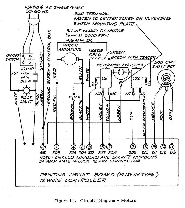
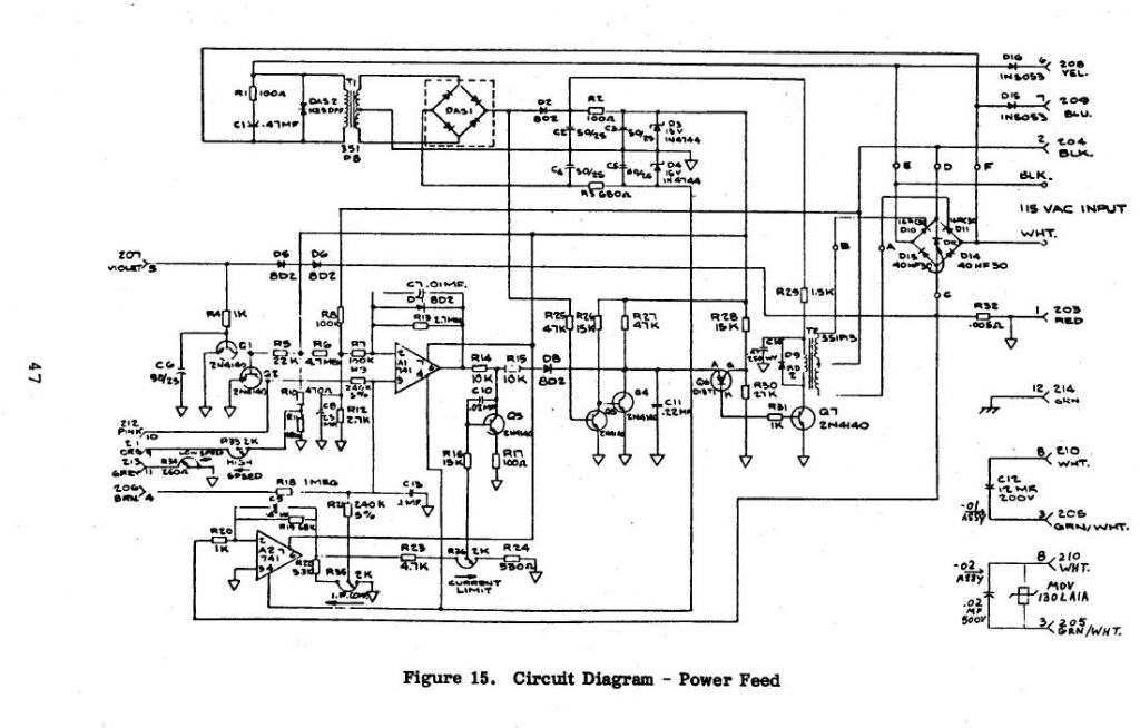
                      Don't know which ones you've been given as I can't read your PMs. However, from an early US manual here is one schematic for power feed. Sounds as if it's probably different to yours but it's quite interesting. The old 741 opamp is in there along with lots of old transistors. Quite a lost art designing that kind of stuff…

                      power feed 1.jpg

                      power feed 2.jpg

                      Merry

                      #135577
                      john fletcher 1
                      Participant
                        @johnfletcher1

                        I have copy of the Erskine PCB layout with all the component values, if you send me an email with your address and phone number I will post you a copy and explain a few details. The table motor is a 110 volt DC shunt wound motor and to test it I fixed up a yellow 110 volt power tool transformer and a bridge rectifier, you can see where the 4 wires go inside of the control box. Mark the 4 wires that go to the table motor and disconnect them. Then connect them to the temporary 110 volt supply. One of the faults I have found is the variable (pot) speed controller failure, its an easy job to change.Another fault is a resistor on the board over heater, you can see by the burn marks it should be green ceramic colour,it needs a higher wattage if you have to change it as it might be open circuit. I haven't fixed one for a long time and can't rember other details, but as the day goes on I'll get back to you.Ted

                        #135584
                        KWIL
                        Participant
                          @kwil

                          Richard, I have a copy of the Service Manual for the Bridgeport Erskine Drive PM your email

                          #135626
                          Richard Clark 1
                          Participant
                            @richardclark1

                            Hi to all,

                            A big thanks for everyone that is replying to this as it will make everything a bit easier im sure.

                            If this forum made cutting oil it would probably be the best cutting oil in the world !!

                            Regards

                            Richard..

                            #144762
                            Mark Willis
                            Participant
                              @markwillis73847

                              Hi, does any one have a circuit diagram for the F6 feed PCB, ie the UK version which differs from the USA version as per the manuals show and is reproduce above, mine is a "Easkine revision 4" … I am particularly interested in finding out the value of R6 as mine has been damaged (burnt out) due to a micro switch problem.. and comparing other values from the PCB they dont match the circuit diagram.

                              Many Thanks Mark

                            Viewing 13 posts - 1 through 13 (of 13 total)
                            • Please log in to reply to this topic. Registering is free and easy using the links on the menu at the top of this page.

                            Advert

                            Latest Replies

                            Home Forums Manual machine tools Topics

                            Viewing 25 topics - 1 through 25 (of 25 total)
                            Viewing 25 topics - 1 through 25 (of 25 total)

                            View full reply list.

                            Advert

                            Newsletter Sign-up