do i need reverse

Advert

do i need reverse

Home Forums General Questions do i need reverse

Viewing 25 posts - 1 through 25 (of 96 total)
  • Author
    Posts
  • #185928
    kevin large
    Participant
      @kevinlarge76611

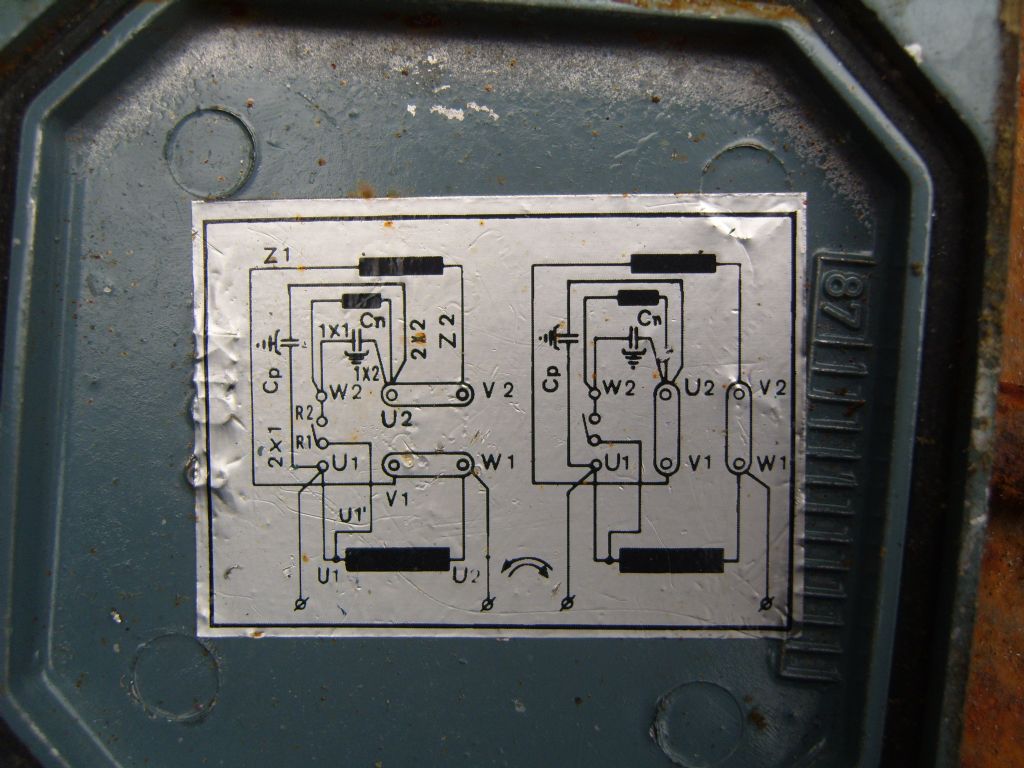
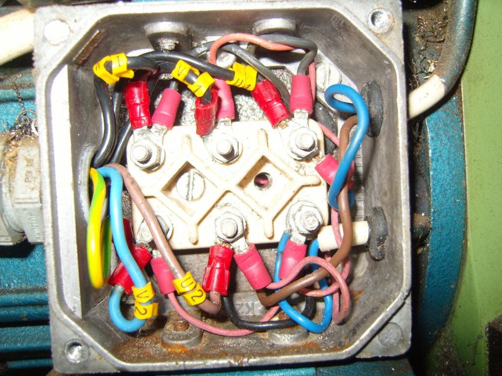
      20150409_175446[1].jpg20150409_175439[1].jpg20150409_175416[1].jpg20150409_074115[1].jpg

      Advert
      #23806
      kevin large
      Participant
        @kevinlarge76611
        #185929
        kevin large
        Participant
          @kevinlarge76611

          ive removed the switch

          #185931
          kevin large
          Participant
            @kevinlarge76611

            the above is how its wired now in the top pics the white lead goes straight to plug hope these pics help if more pics will help just let me know

            #185945
            Nicholas Farr
            Participant
              @nicholasfarr14254

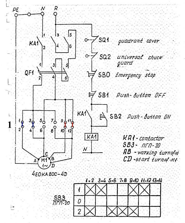
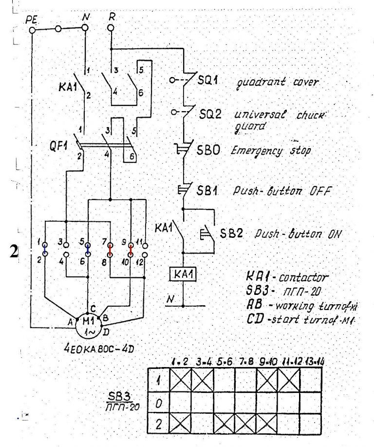
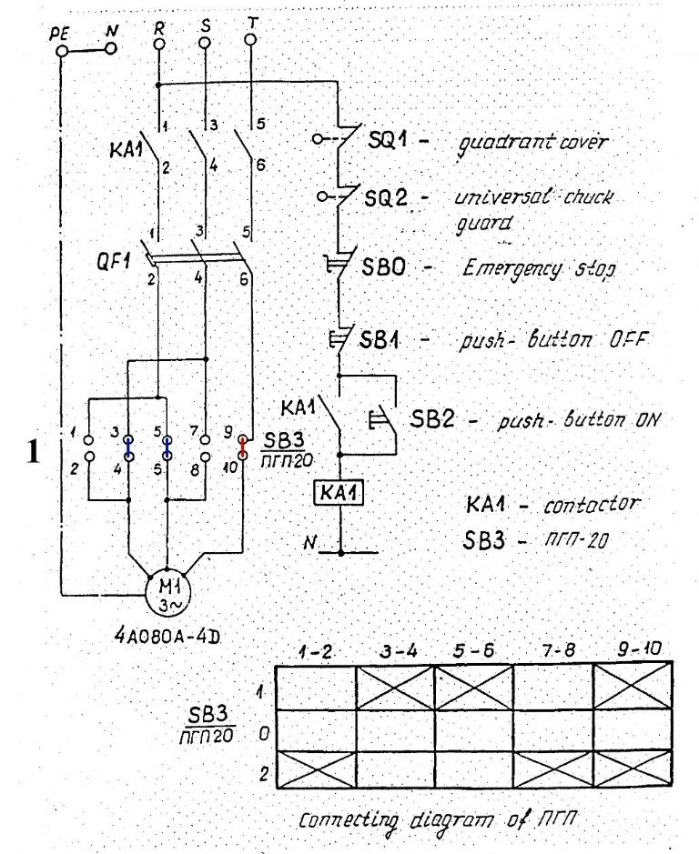
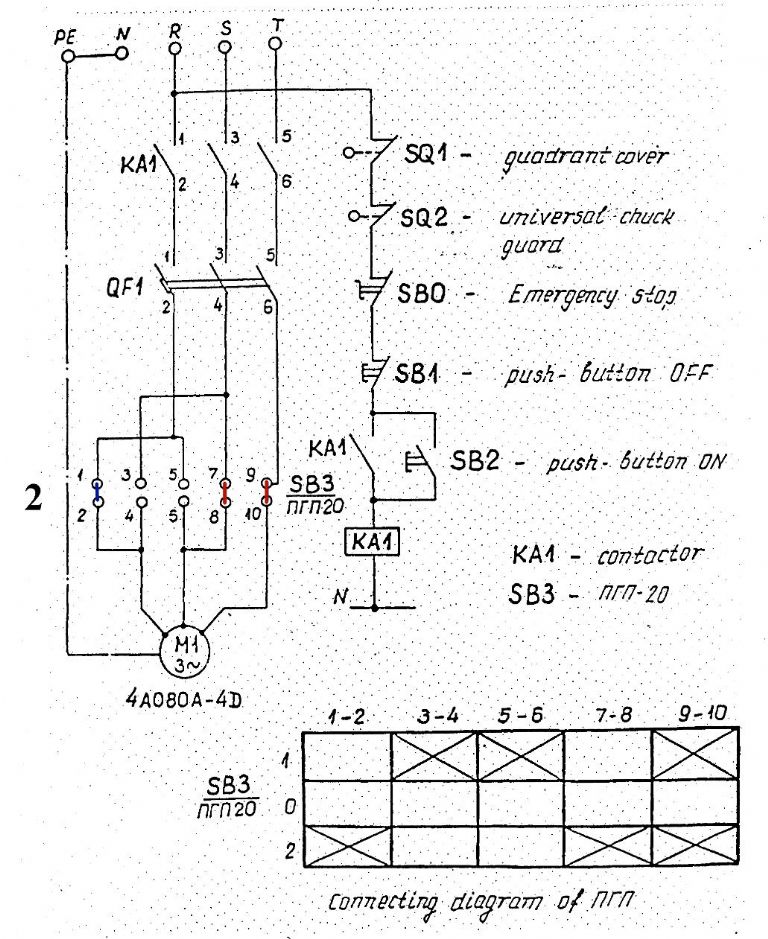
              Hi Kevin, looks like it has been bodged up a bit and it isn't as safe as it should be as the NVR contactor is missing. Below are scans of the circuit diagram. The first two show how the forward/reverse lever makes the connection ditto on SB3/nrn-20 on a single phase motor and the second two shows the same on a three phase motor.

              I'm guessing that QF1 may also be missing which is an overcurrent protection.

              220w1.jpg220w2.jpg


              Regards Nick.

              Edited By Nicholas Farr on 09/04/2015 21:07:01

              #185948
              Nicholas Farr
              Participant
                @nicholasfarr14254

                220w3.jpg

                220w4.jpg

                Regards Nick.

                #185953
                kevin large
                Participant
                  @kevinlarge76611

                  Thanks nick all looks like rocket science to me does that single phase diagram relate to what I have

                  #185961
                  Nicholas Farr
                  Participant
                    @nicholasfarr14254

                    Hi Kevin, the forward/reverse switch appears to be ok, as the same switch is used for either single or three phase, but overall I don't think what you've got relates to either diagram. I think you need to get a competent electrician to look at your options showing the diagrams.

                    Regards Nick.

                    #185972
                    Les Jones 1
                    Participant
                      @lesjones1

                      Hi Kevin,
                      The motor is definitly a single phase motor. IF NO CONNECTIONIONS AT THE REVERSING SWITCH HAVE BEEN CHANGED FROM THE ORIGINAL WIRING then removing the two straps in the motor connection box leaving the existing wires connected to U1 and U2 and connecting the two black wires that have been cut off to terminals V1 and Z2 (Middle top and bottom right) should work. Before trying this can you confirm that the motor runs forward with the reversing switch in both forward and reverse positions and that in the middle of position the motor is stopped. (Assuming there is a middle off position.) I have just read your comment about the mains being connected directly to the reversing switch. In view of this I agree with Nick that you need a competent person to re wire it as in the diagram so you have the NVR function and the interlocks working.

                      PS I've Just realised why there are two diagrams for single phase operation. One shows the path through the reversing switch for forward. The other shows the paths for reverse.

                      Les.

                      Edited By Les Jones 1 on 09/04/2015 23:06:37

                      #185982
                      kevin large
                      Participant
                        @kevinlarge76611

                        Hi les
                        at the moment the motor only runs forward in the reverse position nothing in the off nothing in the forward

                        #185997
                        Les Jones 1
                        Participant
                          @lesjones1

                          Hi Kevin,
                          Either the wiring on the reversing switch has been changed or the motor has been connected to one of the pair that should go to the main winding (2 and 10 on the reversing switch if it is wired as in the diagram) and one of the pair that would go to the auiliary winding (4 & 6 for one of the wires and 8 &12 for the other wire on the reversing switch if it is wired as in the diagram) Does your lathe have an electrical box containing the contactor (KA1 on the diagram) and the thermal overload unit (QF1 on the diageam) ? Also does it have the start and stop buttons and the interlock switches ? I think you need to get someone on site with electrical knowledge.

                          Les.

                          #186000
                          kevin large
                          Participant
                            @kevinlarge76611

                            Hi les it does not have start and stop button box it does have red panic button nothing else that I can see I’ve try ed 2 electrician so far but they didn’t seem to have much idea
                            kevin

                            #186001
                            Les Jones 1
                            Participant
                              @lesjones1

                              Hi Kevin,
                              You need an electrician with a knowledge of motors or someone like a number of members of this forum with reasonable electrical knowledge. Not just an electrician that can only wire houses. It is possible that the box with the start buttons and contactor have been removed. It is also possible that it was never fitted. If the panic button is the latching type and the contacts rated high enough for the motor current it could have been wired without the stop start buttons and contactor. From some threads on this forum I think some Myford lathes just had a Dewhurst reversing switch without any NVR unit or thermal overload. My lathe (Chester DB10G) was not fitted with thermal overloads.

                              Les.

                              #186004
                              kevin large
                              Participant
                                @kevinlarge76611

                                Hi les thanks for all your help I don’t know how was originally wired it is an early model don’t know exactly there must be a no. Somewhere
                                kevin

                                #186019
                                Nicholas Farr
                                Participant
                                  @nicholasfarr14254

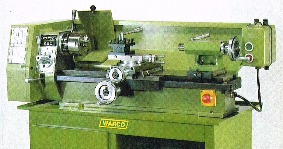
                                  Hi Kevin and Les, as far as I'm aware all Warco 220 lathes came with the contactor box wired in. The photo below shows this box situated at the right hand end of the splash back.

                                  Warco 220

                                  The Warco 220 is the same as the Mashstroy 210T and the emergency stop is wired integral within the lathe itself and can be seen at the right hand end of the bed. I think at some time in its past, the contactor box had developed a fault and someone has just removed it and put a plug on the end of the flex that went into the box. Peter G. Shaw did a write up in MEX 192 of how he repaired a fault on his own Warco 220 lathe contactor box.

                                  Regards Nick.

                                  #186045
                                  Les Jones 1
                                  Participant
                                    @lesjones1

                                    Hi Nick,
                                    I agree with your theory about the original contactor box being removed. I think Kevin should at least have an NVR even if he does not have thermal trips.I suspect the reversing switch is wired as in your diagram as the links between terminals on the reversing switch that are visible in Kevin's photos tie up with the diagram. I suspect that one connection on the motor is connected to one of the main winding wires and the other connection connected to one of the auxiliary winding wires. This would explain why the motor only runs in one position of the reversing switch. In the other position the two motor connections will be connected to the same leg of the mains. I think it would be too difficult to talk Kevin through identifying the 4 wires from the reversing switch to the motor using a multimeter. (Even if he has a multimeter.)

                                    Les.

                                    #186048
                                    kevin large
                                    Participant
                                      @kevinlarge76611

                                      I do have a multi meter if it helps

                                      #186066
                                      Les Jones 1
                                      Participant
                                        @lesjones1

                                        Hi Kevin,
                                        If you want to try to identify the the wires to the motor nere is how to go about it.

                                        FIRST UNPLUG THE LATHE FROM THE MAINS.

                                        Set the reversing switch to the middle off position.

                                        Disconnect one of the wires that is connected to the motor in the motor connection box. (This is to avoid the winding resistance from confusing your readings as it will only be about 5 ohms.)

                                        Confirm that there is only one wire connected to terminal 2 on the reversing switch. Use your meter to identify which wire this is in the motor connection box and label this "A"

                                        Confirm that there is only one wire connected to terminal 10 on the reversing switch. Use your meter to identify which wire this is in the motor connection box and label this "B"

                                        Confirm that terminals 4 and 6 are linked together on the reversing switch and there is only one other wire connected to this point.. Use your meter to identify which wire this is in the motor connection box and label this "C"

                                        Confirm that terminals 8 and 12 are linked together on the reversing switch and there is only one other wire connected to this point.. Use your meter to identify which wire this is in the motor connection box and label this "D"

                                        Confirm that terminals 1, 3 and 7 are linked together on the reversing switch and there is only one other wire connected to this point.. I expect this to be live or neutral of the wire from the mains plug. Make a note of which one it is.

                                        Confirm that terminals 5, 9 and 11 are linked together on the reversing switch and there is only one other wire connected to this point.. I expect this to be live or neutral of the wire from the mains plug. Make a note of which one it is.

                                        When you have done this report the results particularly any difference to what I expected.

                                        Les.

                                        #186087
                                        Nicholas Farr
                                        Participant
                                          @nicholasfarr14254

                                          Hi Kevin, if you can check all the connections as Les has suggested, I think you will find they are all correct as I've studied your photos again and they look to be right, but you do need to make sure.

                                          In the meanwhile and this may help Les more than yourself, I have been able to lift the cover on mine and your connection block is not all that different. The links shown in my diagram, have not be used in the wiring.

                                          s1030611.jpg

                                          In the photo below the block is designated as follows, from top left to bottom right and reading left to right. W1 V1 U1 # V2 U2 W2

                                          s1030617.jpg

                                          Mine also has two capacitors, but I don't know their values, but one is physically slightly smaller. The larger one comes in though the top grommet on the right hand side and the smaller one comes through the bottom grommet on the right hand side. The wiring coming in from the left hand side is from the forward/reverse.

                                          I'm sure yours can be corrected from all this info, but I do agree with Les that you really do need an NVR for safety reasons as much as anything else.

                                          Regards Nick.

                                          Edited By Nicholas Farr on 11/04/2015 10:45:41

                                          #186125
                                          kevin large
                                          Participant
                                            @kevinlarge76611

                                            Hi led and nick I have checked all the connection s 3 times and all is lie you said 5 9 11 live 1 3 7 neutral

                                            Kevin

                                            #186126
                                            Les Jones 1
                                            Participant
                                              @lesjones1

                                              Hi Kevin,
                                              Have you identified and labeled the 4 wires in the motor connection box ? If so here is the next task to confirm that the reversing switch is working as it should be. You need to create a table for each of the three positions of the reversing switch to indicate which of the mains plug pins that each of the 4 wires ( A, B, C, D) connect to.

                                              Somthing like this

                                              Forward

                                              A ?
                                              B ?
                                              C ?
                                              D ?

                                              Middle (off)

                                              A ?
                                              B ?
                                              C ?
                                              D ?

                                              Reverse

                                              A ?
                                              B ?
                                              C ?
                                              D ?

                                              You will replace the question mark with either L (Live), N (Neutral) or NC (No connection)

                                              When I have confirmed that the results of these tests are as expected I will tell you how to connect the 4 wires to the motor terminals.

                                              The tests that you have done so far confirm it is wired as in the diagram Nick posted. (Apart from the strarter being removed)

                                              Les.

                                              Nick,
                                              The diagram in Kevin's motor makes it very clear how to wire it up.

                                              Les.

                                              #186128
                                              Nicholas Farr
                                              Participant
                                                @nicholasfarr14254

                                                Hi Kevin and Les, I traced my wiring out on my forward/reverse switch today and found that it differs slightly from the diagram. The numbers on mine are in different positions to Kevin's, but the switched contacts still match up to the same numbers in the box diagram. I've put a couple of photos of the wires to the switch and a F and R circuit diagram plus a diagram of the links attached to the switch in my Warco album **LINK** I haven't included the contactor or the circuit breakers with them, as they are the same as the manuals diagrams, just hope you can read my pen drawings OK.

                                                Regards Nick.

                                                Edited By Nicholas Farr on 11/04/2015 20:58:50

                                                #186159
                                                kevin large
                                                Participant
                                                  @kevinlarge76611

                                                  Hi les nick I label wires a b c d no conect ions in off position a neutral b live in reverse and forward no other conect ions
                                                  Kevin

                                                  #186187
                                                  Les Jones 1
                                                  Participant
                                                    @lesjones1

                                                    Hi Kevin,
                                                    From those results It looks like 4 sets of contacts on the reversing switch are not working. Can you test for continuity directly on the switch in both forward and reverse between these 4 pairs of terminals 3 and 4. 5 and 6, 7 and 8, 11 and 12 and post the results. Also which two of the wires A, B, C, D were connected to the motor terminals ?

                                                    Can you confirm that this is the table you created.

                                                    Forward

                                                    A —– N
                                                    B —– L
                                                    C —– NC
                                                    D —– NC

                                                    Middle (off)

                                                    A —– NC
                                                    B —– NC
                                                    C —– NC
                                                    D —– NC

                                                    Reverse

                                                    A —- N
                                                    B —- L
                                                    C —– NC
                                                    D —– NC

                                                    It is correct that there are no connections in the off position of the switch.

                                                    Les.

                                                    Edited By Les Jones 1 on 12/04/2015 16:22:18

                                                    #186208
                                                    kevin large
                                                    Participant
                                                      @kevinlarge76611

                                                      Hi les table correct the wires connected where and d no continuity between 4 sets of terminals
                                                      kevin

                                                    Viewing 25 posts - 1 through 25 (of 96 total)
                                                    • Please log in to reply to this topic. Registering is free and easy using the links on the menu at the top of this page.

                                                    Advert

                                                    Latest Replies

                                                    Home Forums General Questions Topics

                                                    Viewing 25 topics - 1 through 25 (of 25 total)
                                                    Viewing 25 topics - 1 through 25 (of 25 total)

                                                    View full reply list.

                                                    Advert

                                                    Newsletter Sign-up