reverse dis-assembling a rotary table

Advert

reverse dis-assembling a rotary table

Home Forums Manual machine tools reverse dis-assembling a rotary table

Viewing 7 posts - 1 through 7 (of 7 total)
  • Author
    Posts
  • #513164
    Iain Downs
    Participant
      @iaindowns78295

      I was debating in another thread if I wanted a compressor or a rotary table for Christmas. As my birthday is shortly after Xmas, the compressor I fancied had 30% off on black Friday and a kind Forum member responded to my Wanted, i have got both!

      Rightly or wrongly I decided to take the table apart to clean it up (and also see what I bought). The table is and 8 inch horizontal / vertical from Excel in Coventry probably from around 1990 (+/-5 years) based on the phone number format of the label.

      As the subtitle indicates I didn't take an pictures stripping it down, so imagine this backwards!

      Firstly, when I got it apart, there was a lot of caked on gunk inside, mainly on the gear, but also on the flats which were the main bearings. I think this was due it not having been used for a LONG time.

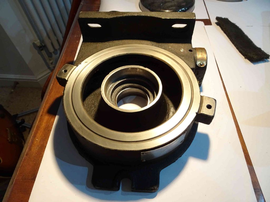
      This is the base.

      rotary base.jpg

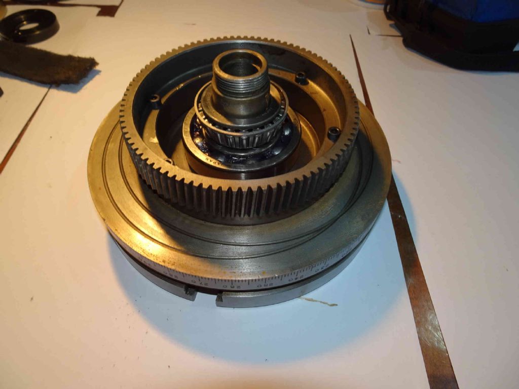
      And this the table

      rotary table with bearings.jpg

      you can see here that it's a substantial machine. as well as the cast iron bearing surfaces with nice oil channels, it has a standard bearing at the top and an angular bearing at the bottom.

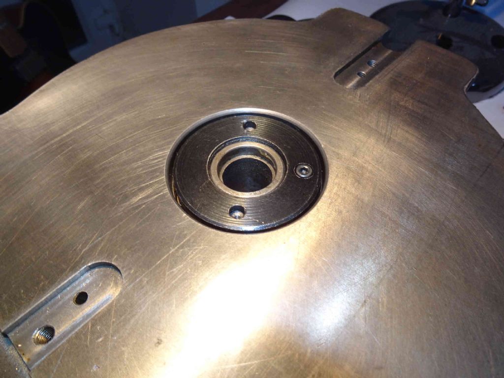
      The whole assembly is held together with a threaded washer thing with a set set screw to hold it steady.

      rotary base with preload.jpg

      I haven't fully understood this part. The washer is split in half horizontally where the set screw is. The exact position of the washer and force on the set screw has a fairly delicate relationship with the movement of the table. A few millimeters more turn and the table is jammed. Excel were kind enough to send me a user guide for their current table (which may or may not be this one), but it didn't cover strip down.

      However, however I managed to do it I seem to have ended up with good results.

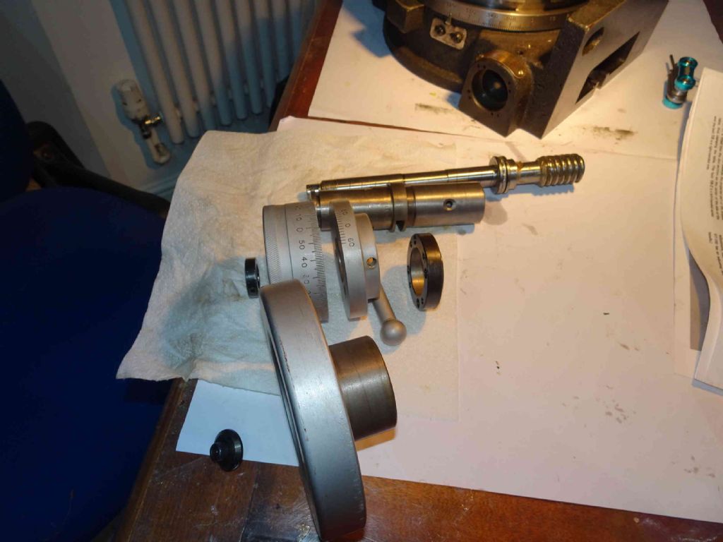
      Rather than do a blow by blow of the worm and handle assembly, here is a kind of exploded view.

      rotary drive exploaded.jpg

      what I found was that you can't put the worm in with the table in place. This, of course after I'd put all of that together!

      It's a bit blurry so… just in from the of the worm is a thrust bearing and washers. This goes inside the next bit down which is bored offset so you can rotate the whole worm to bring it in contact with the rack (I suppose it's a rack?) or not.

      the ring in front of the grey bits bolts to the base. It appears to have set screws to adjust the exact fit, but I just made sure it went back the same way!

      The ring behind that lot screws into the rack and holds the whole lot together. acting as a thrust bearing, I suppose. There are two set screws to fix it in place against the threads. This is rather like what Stefan found in his 6 inch Vertex strip down and I would guess this could be a Vertex.

      The front grey bit there rotates the worm and is used to lock and unlock the worm. It also has the vernier. Behind that is the minutes scale and in front of all is the handle.

      There's also a hole in the side which is meant to have a set screw and a small ball bearing. I think this is there to take up slack of the bore wears, but it's either not there or I lost it taking it out. Perhaps one day I will find it again on my floor.

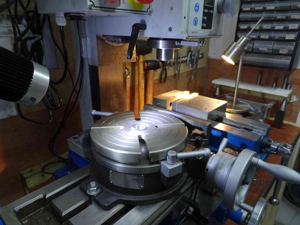
      Here is the table on the mill

      rotary on mill.jpg

      I'm not sure I will keep it on the mil. I've seen people do so but, although it's not too big for the mill it does take up a lot of room.

      I've got it set so the movement is a tiny bit stiff and as far as I can tell there is zero backlash between the handle and table.

      I'm feeling very happy with my purchase and looking forward to my first use. Thank you very much Mr G!

      Iain

      Advert
      #14108
      Iain Downs
      Participant
        @iaindowns78295

        I forget to photograph the real disassembly

        #513188
        old mart
        Participant
          @oldmart

          Thats a very nice table, It will be pretty heavy, so you could make a lifting handle that clamps in the tee slots. I have enough weight in a 6" table for my arthritic joints, I always check that the space in the cupboard reserved for it is free before lifting it off the mill bed.

           The threaded nut which is split where the locking setscrew sits allows the threads to move apart, changing their pitch to lock on the male thread One side of the split has the screwhole and the other side is undrilled.


          Edited By old mart on 12/12/2020 21:20:53

          Edited By old mart on 12/12/2020 21:25:43

          #513197
          Pete.
          Participant
            @pete-2

            Looks good, you'll probably find actual rotary milling is nicer on that than the small 6", I have 9×20 1987 Taiwanese lathe from that same supplier, they're still in business, although I wouldn't ever buy anything from them, appalling customer service.

            #513242
            Oily Rag
            Participant
              @oilyrag

              "There's also a hole in the side which is meant to have a set screw and a small ball bearing. I think this is there to take up slack of the bore wears,"

              Small ball bearings are not used to take up 'slack' in a bore, they would quickly indent any shaft and make it 'brinelled' – they are used generally, especially when backed up by a spring, as a detent mechanism but also maybe used as a locator in rare circumstances. Is there a corresponding drill 'pop', or two, in the shaft?

              #513255
              DiogenesII
              Participant
                @diogenesii
                Posted by Oily Rag on 13/12/2020 12:23:22:

                "There's also a hole in the side which is meant to have a set screw and a small ball bearing. I think this is there to take up slack of the bore wears,"

                Small ball bearings are not used to take up 'slack' in a bore, they would quickly indent any shaft and make it 'brinelled' – they are used generally, especially when backed up by a spring, as a detent mechanism but also maybe used as a locator in rare circumstances. Is there a corresponding drill 'pop', or two, in the shaft?

                I think it's meant to have "setrscrew – ball bearing – setscrew" ..in the sense that the inner screw sets the adjustment, and the ball prevents it from being turned by the outer locking screw…

                #513260
                Oily Rag
                Participant
                  @oilyrag

                  Good point Diogenes!

                  I have found two set screws used in parts like Abwood vice gib adjusters, but bearing directly on each other rather than using an intermediatory ball bearing, I understand your point that a BB would certainly be a way of ensuring no unintended movement. I still think that a brass or ally 'plug' would need to be used at the point of contacting any moving shaft to prevent galling though.

                  Edit for correction of grammar!

                  Edited By Oily Rag on 13/12/2020 14:57:35

                Viewing 7 posts - 1 through 7 (of 7 total)
                • Please log in to reply to this topic. Registering is free and easy using the links on the menu at the top of this page.

                Advert

                Latest Replies

                Home Forums Manual machine tools Topics

                Viewing 25 topics - 1 through 25 (of 25 total)
                Viewing 25 topics - 1 through 25 (of 25 total)

                View full reply list.

                Advert

                Newsletter Sign-up