Myford 254 thread dial indicator

Advert

Myford 254 thread dial indicator

Home Forums Workshop Tools and Tooling Myford 254 thread dial indicator

Viewing 16 posts - 26 through 41 (of 41 total)
  • Author
    Posts
  • #464512
    DC31k
    Participant
      @dc31k

      Derek,

      If you have a 3D printer, the world is your lobster as your namesake once said.

      There is a free program called GearDXF which will give you a 2D dxf file of any gear for which you give it the correct parameters. You can then extrude this for your 3D print. So you can give it the correct module for 3mm pitch and the correct pressure angle (15 degrees). Have a think how you will secure it to its shaft and incorporate a keyway if required.

      The 35t will do both threads but needs different graduations on the dial. For 1.25mm pitch , you will need 5 graduations, that will be spaced every seven teeth of the gear. For 1.75mm pitch, you will need seven graduations, spaced every five teeth of the gear. That is why the dial faceplate needs to be removable and reversible (and positively located on the spindle). Again, this could very easily be 3D printed.

      Advert
      #464529
      SillyOldDuffer
      Moderator
        @sillyoldduffer

        Couple of points,

        Steve Crow has a thread running at the moment on rack cutting gear wheels. The method has been discussed on this forum and is described in detail on the Helicron website.

        Rack cutting is the cheapest way of home cutting a metal gear and its not difficult to make the necessary cutter. Being able to make any modulus required is a big advantage, the disadvantage is home-made cutters don't last as long as professionally made ones. But rack-cutters do a good job on softer metals and should cut several gears minimum. (My heat-treated silver-steel rack-cutters are into double figures in brass and aluminium.)

        Provided the teeth aren't too small, a 3D printer will make acceptable gears, but – depending on the plastic – they may wear quickly. Who cares? Treat them as disposable! Once the STL is available, print a new one.

        Second point : is it worth doing at all?

        Imperial threads are all defined in Turns-per-inch. With TPI there's a straightforward relationship between spindle and lead-screw. A Thread Dial Indicator that helps the operator reposition the cutting tool correctly into a thread is easy-peasy to design and use.

        Unfortunately Metric threads are all defined in pitch. In this system the relationship between spindle and lead-screw isn't straightforward. My metric mini-lathe came with three different TDI gears and care was needed using them. My metric WM280 has a single TDI wheel, but the TDI doesn't cover all the metric threads the lathe can produce, including a few common ones.

        As a metric TDI has to be approached with caution, metric lathes may not be fitted with one by design. A different technique is used to cut metric threads. Typically the operator powers in and out of the cut without disengaging the half-nuts.  May be a little slower than using a TDI, but it eliminates mistakes and the need for a TDI. Note the TDI method isn't always faster than reversing out because some threads force the operator to wait for the TDI to make up to a full revolution before re-engaging.

        Is a metric TDI worth having? My answer is 'maybe'. I use mine when it's obviously faster, otherwise I don't bother with it.

        Would be interesting to compare Imperial TDI vs Metric reversing-out in a race to make several hundred studs.

        While Imperial-TDI is likely to be faster, it depends on the operator banging in the half-nuts reliably on cue. Could be a TDI causes more rejects once the operator is bored out of his mind!

        Despite being a metric fanboy, I think TPI threads are one of the few examples of Imperial having a real advantage over Metric.

        Dave

        Edited By SillyOldDuffer on 14/04/2020 10:19:14

        #464531
        Journeyman
        Participant
          @journeyman
          Posted by SillyOldDuffer on 14/04/2020 10:14:00:

          … Is a metric TDI worth having? My answer is 'maybe'. I use mine when it's obviously faster, otherwise I don't bother with it…

          Dave

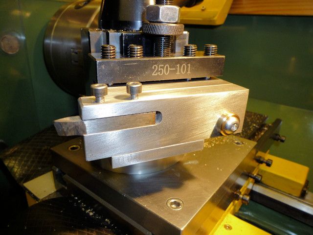
          I can recommend the use of a flip-up tool holder for use on a metric lathe. Provided the lathe has reverse it makes things quicker and saves losing your place winding the cross-slide or top-slide in and out.

          onlathe.jpg

          Details of mine *** HERE *** other write-ups are available.

          John

          #464559
          Derek Greenhalgh
          Participant
            @derekgreenhalgh23299

            Apart from my 3d printer i have an Elexmaker 2500mw laser that can cut thin wood, and a variety of other materials for test purposes, my main problem is cross platform using, i need to keep everything up to date and download and install each program on its proper OS, Windows, Android, linux, as i'm getting on a bit, 63, this is getting more and mire dificult by the day, I've been 3 hours up to now updating windows 10 so I can install geardfx(thanks DC31k) I tend to use an android tablet more and more each day because of this, a bit off topic I know, but its all part of the fix.

            The reason for wanting a TDI is mostly for threading up to a large boss without a fall in groove, you need reflexes when using the non disengage of the half nuts method. I've been meaning to try Joe Pies method of threading out instead of inwards but always in a rush I have never gotton round to it.

            The lathe is built and suplied with the TDI in some countries like australia and used to be suplied here with one but now its not, I even contacted the importers HBM to try to buy one with no luck, they probably discontinued them due to the fact it didn't work as mentioned on all threads. 170$ au + postage from Australia.

            Journeyman, I looked at a build thread of the flipup tool but all the photos, i think photobucket, are missing. I'm sumising the way it works is you flip it up to reverse the lathe and then drop it down for the next pass, I even followed a video link that was no longer available so don't know exactly how its used but think you need a dropin groove to release cutting pressure in order to lift, i may be wrong, Yes i have reverse, just flip a switch, I'll go back and have a look, thanks

            windows10 update 27% done after 3 1/2 hours messing about, I love android.

            Better go wash the dishes before her indoors gets in from work, as a butcher she has a big meat cleaver.

            Thanks for the response @ll, with all this help I'll surely get there

            cheers

            Derek

            #464560
            Derek Greenhalgh
            Participant
              @derekgreenhalgh23299

              oops, double post, sorry

              cheers

              Derek

              Edited By Derek Greenhalgh on 14/04/2020 11:41:33

              #464583
              Martin Connelly
              Participant
                @martinconnelly55370

                This tool retractor can be used without the relief groove as it retracts away from the workpiece.

                Lever operated retractor

                Martin C

                #464591
                SillyOldDuffer
                Moderator
                  @sillyoldduffer
                  Posted by Journeyman on 14/04/2020 10:27:32:

                  Posted by SillyOldDuffer on 14/04/2020 10:14:00:

                  … Is a metric TDI worth having? My answer is 'maybe'. I use mine when it's obviously faster, otherwise I don't bother with it…

                  Dave

                  I can recommend the use of a flip-up tool holder for use on a metric lathe. Provided the lathe has reverse it makes things quicker and saves losing your place winding the cross-slide or top-slide in and out.

                  onlathe.jpg

                  Details of mine *** HERE *** other write-ups are available.

                  John

                  Excellent idea! I've downloaded the PDF plan. If I've got stock, I'll make one. (Was getting ready to visit my local metal Emporium when the lock-in started.)

                  I recommend John's "Journeyman's Workshop website" to everyone – well worth a look!

                  Ta

                  Dave

                  #464620
                  Journeyman
                  Participant
                    @journeyman

                    Dave: Thanks for the plug!

                    Derek: Don't know why you cant see the images, they are all self hosted, no PhotoBucket involved. Try ctrl F5 key combo to refresh the browser.

                    John

                    #464638
                    Harry Wilkes
                    Participant
                      @harrywilkes58467

                      Might be worth a try link

                      H

                      #464646
                      Nigel McBurney 1
                      Participant
                        @nigelmcburney1

                        ref DC31ks comment on chinese gear cutters having the number of cutter relative to the no of teeth gear it will cut are reversed,does this reversal apply to metric cutters compared to old imperial cutter system.,if so In Machinerys handbook 23 rd edition page 1794 there is a note stating that the numbering of module gear gear cutters is reversed compared to the imperial system.

                        #464658
                        Derek Greenhalgh
                        Participant
                          @derekgreenhalgh23299

                          John, the thread i was looking at earlier with missing pictures i think was your original build thread from a good few years ago, not the one you linked to on your website(bookmarked for further reading) I spent over an hour on your site, i git sidetracked, some very interesting builds and other info there that i will be back to in the future.

                          As to chinese module cutters being marked in reverse i have seen both types mentioned in videos, also when you order a full set you might not get a full set, This Old Tony ordered a set and of the 8 he got 2 were missing but repeated getting 2x of other numbers, its pot luck and a long time to wait too, especially the way the world is today with this pandemic.

                          I got geardfx installed and a 35 tooth gear in .stl form ready to print but its thundering and lightning here atmo so I don't want to start it as living in a very rural part of spain we often get power cuts, its the price we pay por peace and quiet.

                          cheers

                          Derek

                          #464667
                          duncan webster 1
                          Participant
                            @duncanwebster1

                            Unless you're going to do a lot of screwcutting I'd stick with the leave the halfnuts engaged method. By the time you've fiddled about fitting the right gear to the indicator and then the right dial on the top and then adjusted the mesh you'd have finished the job. You do after all have power reverse. The real Myford gears are I think helical, another problem if you think of cutting your own. Of course if you make it very thin it won't matter.

                            #464675
                            Journeyman
                            Participant
                              @journeyman
                              Posted by Derek Greenhalgh on 14/04/2020 17:48:05:

                              John, the thread i was looking at earlier with missing pictures i think was your original build thread from a good few years ago, not the one you linked to on your website(bookmarked for further reading) I spent over an hour on your site, i git sidetracked, some very interesting builds and other info there that i will be back to in the future…

                              Derek

                              Derek, nowt to do with this thread really but a possible explanation. There never was a separate build thread, but several years ago I discovered that pretty much the whole site had been copied by someone in the China and embedded in some sort of advertising system. They didn't bother to copy any of the images though and simply hot linked to mine. I have subsequently adjusted the server software (Apache) to prevent hot linking. So if for some strange reason you have discovered one of these Chinese efforts you may see the text without images. Very strange place the Interweb!

                              John

                              #464717
                              Derek Greenhalgh
                              Participant
                                @derekgreenhalgh23299

                                Its not for a myford lathe, i sort of hijacked the thread with a similar problem as the OP so as not to have everyone repeat everything. I realize the gear should be slightly helicoidal to fit the leadscrew if deep but thats no problem on a 3d printer if the model is correct, i might be able to do it with the rotary table too by raising the tailstock slightly to the angle, not 100% correct way to do it but i have nothing else to do with my time as i'm a pensioner and also under lockdown due to the pandemic, time is all i have, as its thundering and lightning, raining fir a week so i cannot plough my fields to plant maiz, and nothing on the tele

                                cheers Derek

                                #464728
                                Hopper
                                Participant
                                  @hopper

                                  The threading dial gear is a placeholder only, not transmitting any load at all. So tooth form is not vital. A piece of flat brass plate with square or almost square teeth filed on it after careful mark up would do the job.

                                  But a more sophisticated way if a fellow did not have the perfect gear cutter might be to drill the required number of holes around the periphery of a disc and then turn brass pegs in the shape roughly of an involute curve then insert the pegs into the holes and secure in position, so the piece would look a bit like a ship's helm. On the lathe mentioned with a 3mm pitch lead screw should be a manageable size.

                                  But I agree that reversing the lathe and running the tool back under power with halfnuts engaged is the easiest way if you have reverse.

                                  #465165
                                  Derek Greenhalgh
                                  Participant
                                    @derekgreenhalgh23299

                                    Another way to do single point threading

                                     
                                    could be done with half nuts engaged from start to finish without the hard stop
                                     

                                    Edited By Derek Greenhalgh on 17/04/2020 08:25:07

                                  Viewing 16 posts - 26 through 41 (of 41 total)
                                  • Please log in to reply to this topic. Registering is free and easy using the links on the menu at the top of this page.

                                  Advert

                                  Latest Replies

                                  Viewing 25 topics - 1 through 25 (of 25 total)
                                  Viewing 25 topics - 1 through 25 (of 25 total)

                                  View full reply list.

                                  Advert

                                  Newsletter Sign-up