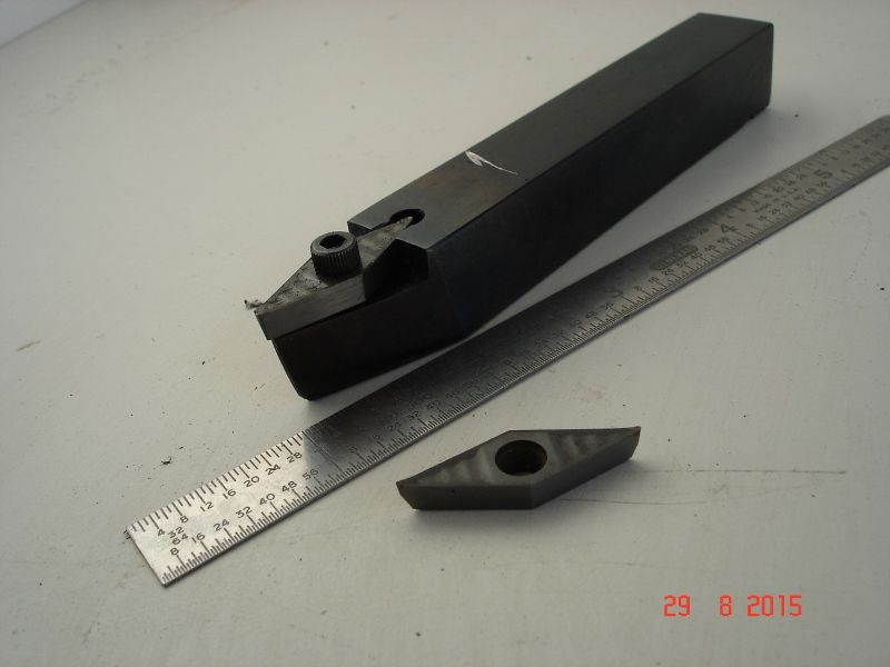
Insert tip query
Insert tip query
- This topic has 24 replies, 8 voices, and was last updated 8 May 2016 at 12:51 by
Raymond Anderson.
Viewing 25 posts - 1 through 25 (of 25 total)
Viewing 25 posts - 1 through 25 (of 25 total)
- Please log in to reply to this topic. Registering is free and easy using the links on the menu at the top of this page.
Latest Replies
Viewing 25 topics - 1 through 25 (of 25 total)
-
- Topic
- Voices
- Last Post
Viewing 25 topics - 1 through 25 (of 25 total)
Latest Issue
Newsletter Sign-up
Latest Replies
- An Unexpected Message
- Chimney turning
- Milling for beginners book, Where?
- Arc’s 25mm indexable end mills…
- Parting off on a mini lathe
- Swing over bed limitation for flywheels
- Bridgeport Series 1, table power feed.
- Alternatives for a DRO display change
- Play on warco mini lathe saddle
- Safe and secure way to suspend a 5″G Tender


