Faircut lathe tidy up
Faircut lathe tidy up
Home › Forums › Manual machine tools › Faircut lathe tidy up
- This topic has 123 replies, 9 voices, and was last updated 1 October 2020 at 14:14 by
Brian Morehen.
-
AuthorPosts
-
19 May 2020 at 17:58 #473055
Brian Morehen
Participant@brianmorehen85290Hi Jacob,
My toolpost is the same as Andy,s Why yours has a base on it is puzzle that is why i wonder if it has been ,made or altered. , Using your leadscrew when cutting a lenght of bar I often use mine this way saves time a seems to produce a more even finish . only problem is you have to stop this at the right place unless you have a automatic stop on the leadscrew that disengages the dog clutch you do not have to stop the motor. Ihave a toolpost that fits onto my cross slide with spacer that fits beneath it and gives the correct height for cutting of the cross slide at the back. I also have all the gears and bits if you requre any further info.let me know
Regards Brian
19 May 2020 at 17:58 #473056Andy Carlson
Participant@andycarlson18141It occurred to me that '14DP' gears isn't the whole story. You also need to know the pressure angle. Google tells me that this can be estimated from some measurements of the gears. I haven't done that… but I see you have a good few change wheels mounted on your lathe. The likely answers are 14.5 or 20 degrees. 20 degrees is (apparently) more common but it's also possible that Faircut copied the spec from, for example, Drummond who used a 14.5 degree pressure angle 14DP gear.
Edited By Andy Carlson on 19/05/2020 18:00:36
20 May 2020 at 12:59 #473236Jacob Leonidou
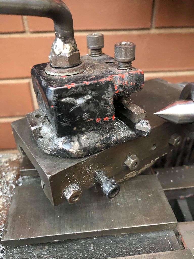
Participant@jacobleonidou84012OK upon further investigation i realised that my tool post is 100% 'home-made', and not even the good kind. In my head i pictured it very differently, and you are right, they are nothing alike.
Standard 1/4 tooling is obviously not right, either.
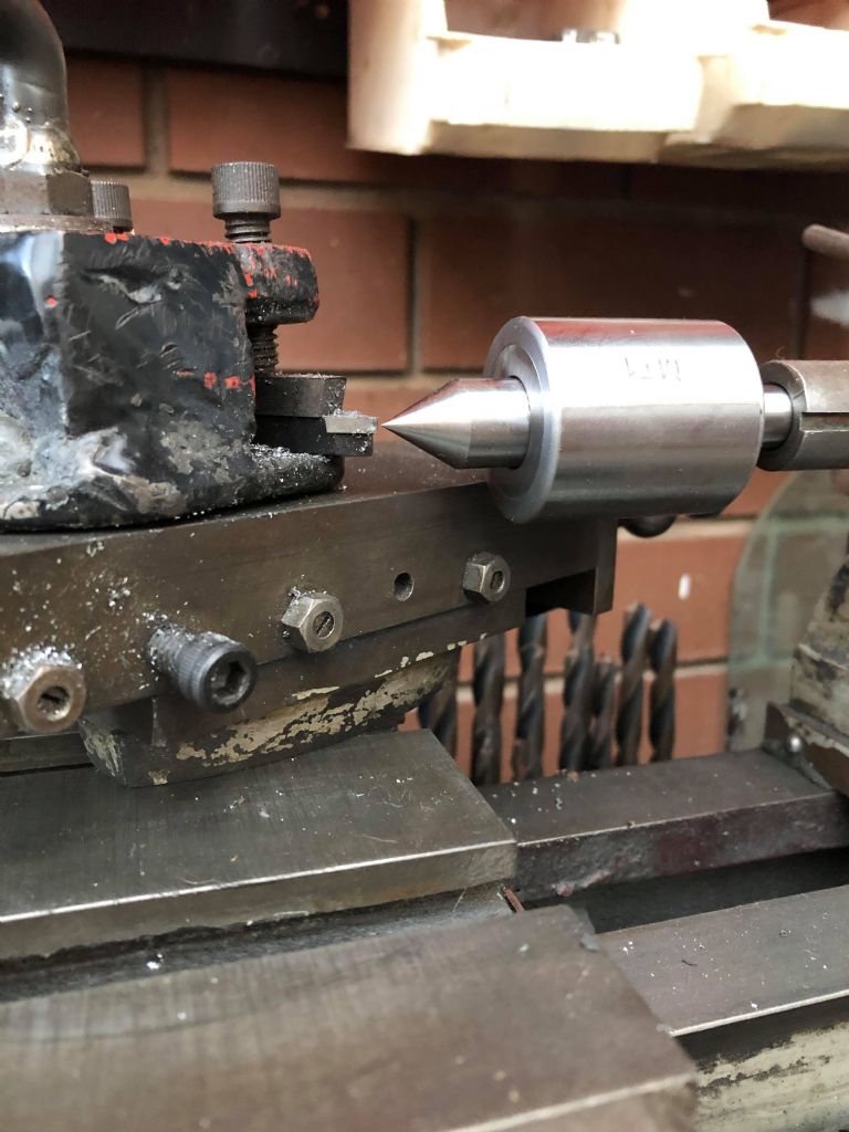
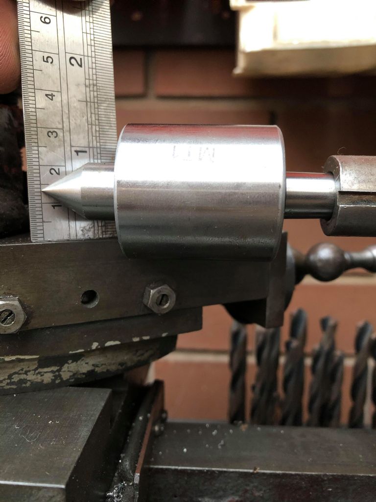
 This shows me that centre height is 13mm approx without the base. I am so confused as to why anyone would be limiting their tooling to less than 1/4 instead of the factory 3/8 or so. Considering i have 13mm to play with im wondering why i dont just buy 1/2 tooling. Anyone had any luck with that? Or opinions as to why or why not?
As for the screw cutting gears, im realising i know absolutely nothing. I dont have any experience with screw cutting whatsoever, so i thought i required additonal gears. Im getting the impression that i have most of them, though i would need to change them around to get the desired speed. Is this correct? I dont even have any reference to know what combinations to use. I need to do some more research.
Also Brian, I thought the same, though when reading about it i noticed that a lot of people advised against using the leadscrew for power feed. Apparently is puts too much pressure on the leadscrew and can wear it out, causing issues with precision. What are your thoughts?
20 May 2020 at 17:30 #473324Andy Carlson
Participant@andycarlson18141Hi Jake,
Half inch tooling fits my toolpost pretty well. I do sometimes need to shim the rear of the tool because the tip sometimes ends up a few thou high otherwise. It's better to check against a dead centre in the headstock because your tailstock aim could be off (mine needed a few shims).
The change gears are just a construction set so that you can build whatever you need, either for screw cutting or for power feeding when turning. They are basically the same thing – power feeding can be thought of as cutting a very very fine thread.
You probably have more than half of a full set of change gears there but you will likely be missing some.
As far as I can tell I have a full set. I have 2 off 20T and then 1 each in 5T steps up to 65T.
TBH screw cutting is probably getting somewhat ahead of yourself a bit but if you find a Myford screw cutting gear table then it should work fine for the Faircut – both have 8TPI leadscrews I think.
It's easy enough to work the simple ones out though – if you have the same sized gear on your spindle ( 'driver' )as the one on the leadscrew ( 'driven' ) and just a plain spur train in between then they will run at an identical speed and you will get an 8TPI thread. Double the teeth on the driven and you will get 16TPI… and so on. If you have an even number of gears in your train you will get a RH thread, odd number for a LH thread.
For power feed you build a gear train usually using compound gears (2 on one shaft) in the middle of the train to get much more reduction. This is how the gears are set up in your photo.
Power feed or hand feed to drive the lead screw… I don't see that either way will place more or less stress on the leadscrew provided that both are done at a sensible speed – the load comes from the friction on the saddle and the resistance from the thing that you are cutting. You will of course have no feedback via your hands when using power feed so if there is a problem then it could be more severe and with power feed you can also crash the tool etc into the job/chuck/headstock if you don't stop in time.
TBH I very rarely use power feed for turning. I've not (so far) cut a thread on the Faircut but I have cut several threads on my Cowells lathe which is pretty much the same design, just half the size… and metric.
Regards, Andy
Edited By Andy Carlson on 20/05/2020 17:31:04
21 May 2020 at 16:36 #473633Brian Morehen
Participant@brianmorehen85290Hi Jake
Your toolpost rather looks like this has a piece welded on the bottom , looks a little like a untidy weld to me , your 13mm gap beetween your centre and your top slide would allow you to use a 1/2 inch tool if than lump was missing on your toolpost. My Faircut is the Junior , I have checked the gap on my lathe , this just under 10mm or just right for 3/8 Tools.
Regards Brian
25 May 2020 at 13:00 #474796Jacob Leonidou
Participant@jacobleonidou84012Brian,
You are absolutely right. I tried checking the centre height from the chuck like Andy suggested, but i wasn't confident in it's accuracy as the chuck would not grip the taper of the centre properly. It appears that it is just right for 1/2 tooling, though i'm not sure if i should be focusing on 1/2 or 3/8. I don't really know what the practical difference is between the two, and im not finding much information online.
Andy,
I remember you saying you use 3/8 tooling. Is there a reason for this? Do you have a particular preference?
Im realising that screw cutting is going to require a lot of research. I might have to sit on the information for a little while, there is a lot to learn. Thanks for breaking that down for me. it makes it a lot easier to understand. Ill probably ask a few questions as time goes on.
As for the power feed, you make a good point. From what i read there is usually a separate drivetrain for the power feed. Apparently the back pressure from turning puts pressure on the leadscrew, which can cause premature wear in the thread. It sort of makes sense, but perhaps not a real issue considering the 'hobby' nature of the machine and work carried out.
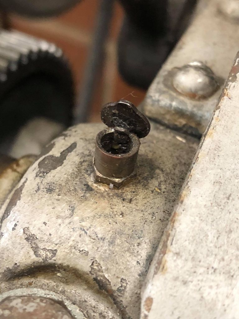
I wanted to share the oil caps, they look factory to me.
Also i was wondering if anyone knew what this add on could be for? Perhaps a provison for spindle locking?
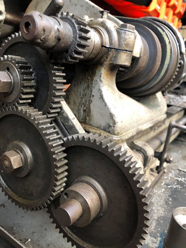
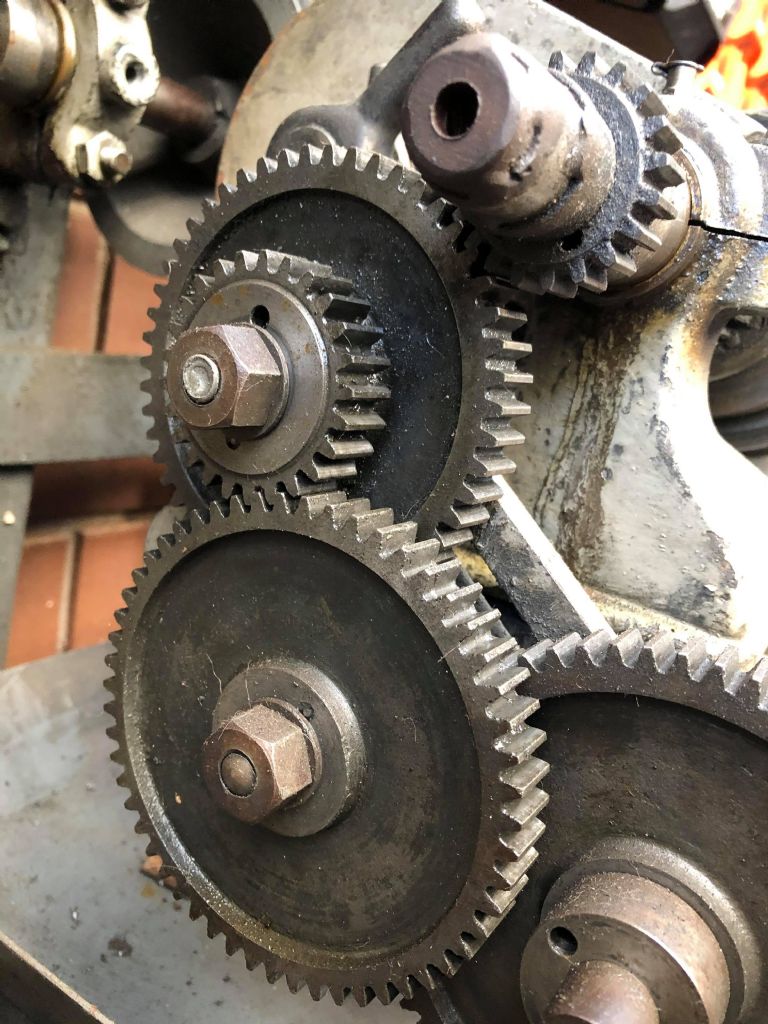
And these are the gear sets close up
 I would like to get around to working out exactly what i have and what threads i can cut with the appropriate combination.
Jake
25 May 2020 at 18:11 #474860Andy Carlson
Participant@andycarlson18141Hi Jake,
In general I use 1/2 inch HSS tooling. I bought a job lot of the things on eBay for not much money. It was a mixed bunch and some were bigger than 1/2 inch but I got enough usable ones to make it a good deal… and an acquaintance with a bigger lathe scored some free tools as well.
I also have smaller lathes that use 1/4 inch tooling so there are times when I put some packing under these and run them in the Faircut. Some 1/2 inch aluminium angle (1/16 thick I guess) is quite good for this because it packs them both below and to the side so that they line up with the clamp screws better. The main tool I do this with is my Arc Euro 6mm boring tool and its square holder… an excellent and inexpensive tool but perhaps not so handy for those down under.
I don't think there is much to say about tool sizes – provided it fits then you can use it. Bigger lathes have bigger tools and can take heavier cuts with them. Bigger tools take longer to grind. Smaller ones will need packing or a QCTP.
I wouldn't rule out your oil cups being factory ones but they are different from mine. My lathe has plain holes and the spigot on the bottom of the oil cup is plain too. If you decide to replace them then don't make the holes in the bearing housing any bigger… which will probably rule out some off the shelf retro fit oilers.
My guess is that the thing on the back end of your spindle may be the remains of a retro fit mandrel handle. These are used to turn the spindle by hand when screw cutting – it gives a lot more control over the stopping position… and is better exercise

Hopefully your mystery 'thing' will unscrew from the spindle. The original factory part in this location is a knurled collar. If you want to replace it then the thread on the tail end of the spindle is 5/8 BSF as far as I can tell. I now have the 'correct' collar on mine but prior to that the previous owner used a metric nut which didn't fit correctly and I replaced that with a proper 5/8 BSF hex nut.
I will probably still use the hex nut from time to time – it allows me to use a 1/2 inch drive socket and a ratchet which I reckon is just as good as having a mandrel handle.
Regards, Andy
25 May 2020 at 18:20 #474861Brian Morehen
Participant@brianmorehen85290Hi Jake
When you move and lock the gears you then disconect the dog clutch and then you will engage the back gear for a very slow speed for screwcutting . Bought both 3/8 and 1/4 tools with my lathe , Most of the 3/8 were high speed and in better condition because the 1/4 were only carbon steel so most off my tools 3/8 for general work..Your Oil cap I think is original as some of mine were the same..A general rule seems to be the lager the tool the better the lathe is i have some1/2 that have been cut down to 3/8 height for cutting 3/8 down to 1/4 Its more a choice of which you prefer good luck the more you try they say the better you get.
Regards Brian
25 May 2020 at 22:35 #474941Andy Carlson
Participant@andycarlson18141Yes the backgear lever is in Jake's photo but I assume he was asking about the home brewed thing on the back end of the spindle.
@Jake… As Brian says, you can engage the backgear to reduce the spindle speed and get lots more torque. The seller may or may not have explained how this works. There are several steps. If you need an explanation then just ask.
Edited By Andy Carlson on 25/05/2020 22:37:41
1 June 2020 at 05:39 #476552Jacob Leonidou
Participant@jacobleonidou84012The more i think about it the more i lean towards the side of using the largest tooling that fits in the post. The way i see it, the larger the tool, the more rigidity in the setup. Besides, I dont even think i can use a QCTP with anything larger than 1/4 tooling. With the current toolpost and its included 'base", 1/4' carbide insert tooling is a 1/2mm too tall. The QCTP inserts would have to have a base that is thinner than the base of my current toolpost to even be at centre. The only option I have for that is to remove the compound and make something work. I've found a few 1/2" insert tool holder sets on eBay that look decent and i might just see if i can borrow a 1/2" tool in the meantime the ensure i'm at or below centre. My tailstock tells me i have 13mm but the reading from my chuck is closer to 12mm. Putting the tapered centre in the chuck didnt seem accurate as it didnt grip the taper well.
I think your mandrel handle theory makes the most sense. I might have to research that a bit more, ill have a look through your thread and see if i can see a picture of yours. Is the end of the spindle just a RH thread? Just want to make sure i get it off without damaging anything. Would putting a wrench on the nut be the proper way to hold the spindle steady while removing the chuck? Does the chuck screw off counter clockwise? I read that engaging the backgear for this purpose can damage the teeth on the gears.
I understand the backgear function a lot more now. If i ever get around to screw cutting, and that's a big if, i can ask a few more questions. At this stage i'm still struggling to make sense of all the change gear theory, and work out how i can retrofit gears intended for other machines. In the future i'd like to acquire a full set.
As for everything else, im so close to being somewhat fully operational. I've acquired all my oils, i've made a bunch of adjustments, and i better understand all the little features of the machine. Things like wheel backlash, gib adjustment, tool sizing and slide locking are things i didn't consider for the most part. I appreciate all the help ive received as i now feel like i know enough that i feel confident in what i am doing.
1 June 2020 at 08:18 #476567Andy Carlson
Participant@andycarlson18141Sounds like you are gaining confidence Jake so that is great. I think the best thing you can do is to get on and use the lathe. You will figure out what works well and not so well much better that way.
I need to shim the rear end of 1/2 inch tools to bring them to exact centre height. It's rather puzzling why the lathe would be so close to 1/2 inch clearance but not quite there… but we're unlikely to get an answer to that one.
As you will see from the thread about my lathe, the morse tapers have been the subject of plenty of attention. A finishing reamer (use plenty of oil and turn ONLY clockwise) will clean them up if they are not too bad but there is reason to doubt whether the headstock taper was No 1 Morse when the lathe left the factory. Both of the ones that I have checked have been too badly scored to get a reliable answer.
I've never had or used a QCTP but don't they hang over the edge of the compound so that the tool holders can drop down lower than a conventional toolpost?
The tail end of the spindle is just a bog standard RH thread. If you don't already have one it would be well worth getting hold of a big rubber and plastic strap wrench. This will allow you to get a good grip on your biggest pulley so that you can put some torque on things instead of being tempted to using the backgears to lock the spindle. Using the backgears to lock the spindle risks breaking a tooth.
If you have more questions, either sooner or later then ask away.
1 June 2020 at 08:28 #476569Brian Morehen
Participant@brianmorehen85290Morning Jacob.
I guess your Lathe chuck centre is 13mm to its centre from the bottom of your top slide , this should acomodate a 1/2 lathe tool . To remove your Lathe chuck use the chuck key give a hard tap with the palm of your hand this normally works on my lathe with all chucke and my face plate . The thread is 3/4 BSF Right Hand on my lathe I supose yours is the same . If the palm of your hand does not work a sharp tap with a piece wood may be a little more forcefu.
Good Luck Brianl
1 June 2020 at 08:39 #476571Andy Carlson
Participant@andycarlson18141Posted by Brian Morehen on 01/06/2020 08:28:43:The thread is 3/4 BSF Right Hand on my lathe I supose yours is the same .
I don't think the Junior and 'Senior' are the same here. I measured 7/8 inch and 11 TPI on mine… which matches the numbers for 7/8 BSF although whether it left the factory with exactly a BSF thread form is not so clear. It now has a slight taper to the thread peaks… which may be wear or may be by design to make it easier to get chucks lined up on the spindle.
2 June 2020 at 13:09 #476971Brian Morehen
Participant@brianmorehen85290Hi Jacob
Your Pic 25/05/20. I wonder if this is picture is showing correctly , Your Main drive headstock gear only appears to be half engaged with the driving gear.
This may cause uneven wear on both gears, Hope this is just a picture fault ? i Think some adjustment may be required.
All the Best Brian
4 June 2020 at 10:48 #477403Jacob Leonidou
Participant@jacobleonidou84012Posted by Andy Carlson on 01/06/2020 08:18:10:Sounds like you are gaining confidence Jake so that is great. I think the best thing you can do is to get on and use the lathe. You will figure out what works well and not so well much better that way.
I need to shim the rear end of 1/2 inch tools to bring them to exact centre height. It's rather puzzling why the lathe would be so close to 1/2 inch clearance but not quite there… but we're unlikely to get an answer to that one.
As you will see from the thread about my lathe, the morse tapers have been the subject of plenty of attention. A finishing reamer (use plenty of oil and turn ONLY clockwise) will clean them up if they are not too bad but there is reason to doubt whether the headstock taper was No 1 Morse when the lathe left the factory. Both of the ones that I have checked have been too badly scored to get a reliable answer.
I've never had or used a QCTP but don't they hang over the edge of the compound so that the tool holders can drop down lower than a conventional toolpost?
The tail end of the spindle is just a bog standard RH thread. If you don't already have one it would be well worth getting hold of a big rubber and plastic strap wrench. This will allow you to get a good grip on your biggest pulley so that you can put some torque on things instead of being tempted to using the backgears to lock the spindle. Using the backgears to lock the spindle risks breaking a tooth.
If you have more questions, either sooner or later then ask away.
Seeing the pictures of when you cleaned up your spindle taper gave me absolute chills. I could just imagine making a mistake and rendering the entire machine useless. Kudos to you for getting it done! I do have a rubber strap wrench but im thinking i could just use a spanner over the tail end on the spindle to lock it. Would that be safe?
You might be right about the QCTP. I honestly wouldn't mind buying one but i dont have any idea of where to start. They sell them cheap on ebay but they are for mini lathes, which might be too small. I'm not sure how to check compatibility yet.
Ok so i checked the centre height again by pushing the live centre all the way back so that the flat part of the back squared it up decently on the chuck jaws. Looks like my centre height is 11.5mm. This makes sense considering the fact that you have to shim the back of your cutters up. I also conducted a little experiment by shimming up the back of the 1/4" tool (thanks for the tip) to where it would no longer leave a pip on the face an measured that. It was 11.5mm again. So my question is: do i buy 1/2 tooling and shim the back up every time i change tools, or do i buy 3/8 and use a single 1.5mm shim? I was so close to buying 1/2" tooling i could almost taste the chips.
4 June 2020 at 10:51 #477405Jacob Leonidou
Participant@jacobleonidou84012Posted by Brian Morehen on 01/06/2020 08:28:43:Morning Jacob.
I guess your Lathe chuck centre is 13mm to its centre from the bottom of your top slide , this should acomodate a 1/2 lathe tool . To remove your Lathe chuck use the chuck key give a hard tap with the palm of your hand this normally works on my lathe with all chucke and my face plate . The thread is 3/4 BSF Right Hand on my lathe I supose yours is the same . If the palm of your hand does not work a sharp tap with a piece wood may be a little more forcefu.
Good Luck Brianl
Looks like it is 11.5mm. The 13mm in the tailstock must be due to misalignment unfortunately.
Do you find that you need to lock the spindle at all? Will a hard tap free it without locking the spindle?
Also i had another look and it looks like the teeth are half way engaged? Do you think they need more engagement?
4 June 2020 at 13:15 #477441Brian Morehen
Participant@brianmorehen85290Hi Jacob.
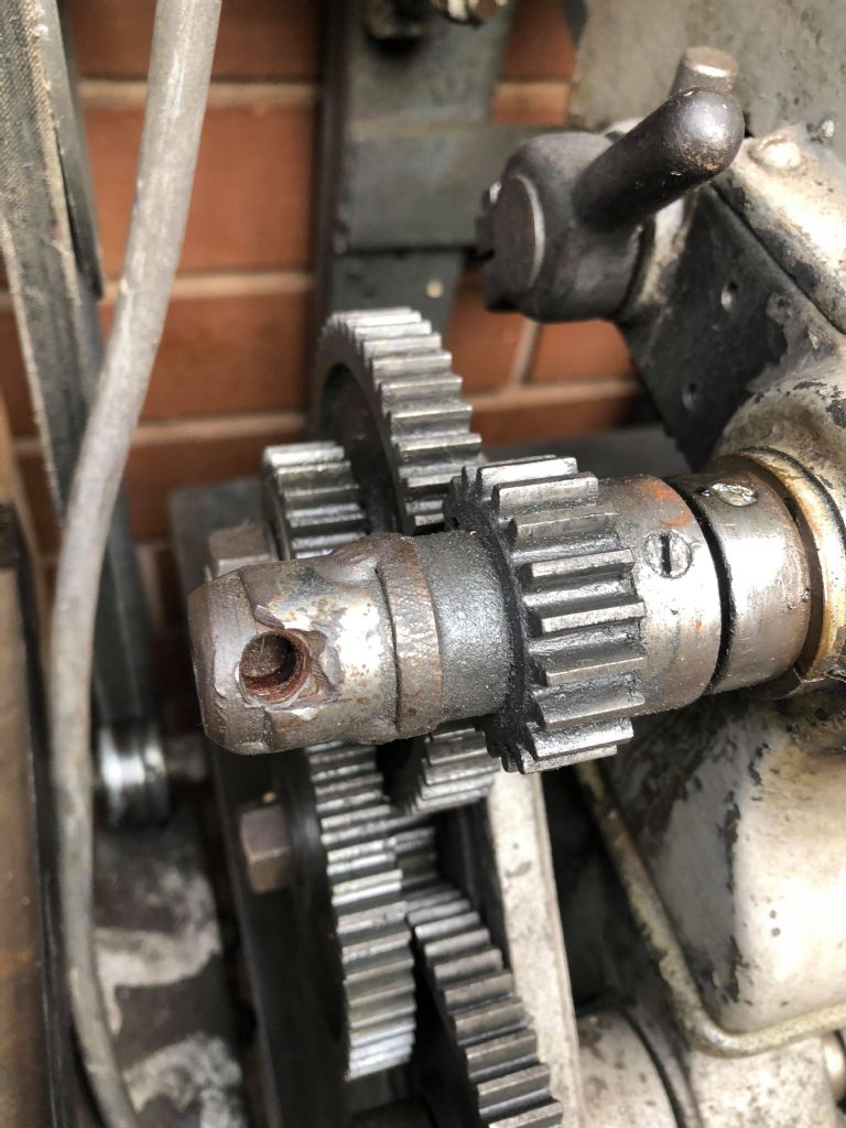
Have not got a Q C T P , All of my tools have been ground to match or are shimed up to , match Some of my 1/4 fit into a tool holder to match a 3/8 centre cutting hight. Chuck removal do not engage the back gear for fear of causeing any damage to the gears or a brocken gear , Your gear that is only half engaged may cause uneven wear on the gears used , If you use all of the gear there will be more strength to adjust to get a full engagement wiil mean you have got to add or remove some spacing or shims that are incorrect,. You have a strange looking piece of metal on the end off your drive shaft with a hole in view looks strange Because the bit in front that has a knurled ring round it is the lock nut that removes any slackness , this also ;looks like this has been welded on and the hole has been used for tightening this arrangement in the past. I think that somewhere on that drive shaft to your chuck near the main gear that provides the drive there is pin that slides out to disengage the drive, This then enables you to engage the back gear if you move the lever towards you. When you remove this pin the chuck runs freely ]Andy may have more info on this because his lathe is the same. My Lathe is the Junior.
Have fun and feel free to ask . Good Luck Brian
4 June 2020 at 13:28 #477445Andy Carlson
Participant@andycarlson18141Hi Jake,
Putting a boring tool into the headstock taper is definitely not a good introductory lathe job. Using a finishing reamer on either the headstock or tailstock taper is much less scary provided you use plenty of oil and only turn it clockwise. It really depends on whether the taper is scored enough to warrant a cleanup. If Brian is correct and the headstock taper is actually Brown and Sharpe (1:24) rather than MT1 (1:20) then putting an MT1 finishing reamer into it might just result in a bell mouthed 1:24 taper… which is why I used the boring tool on mine. The alternative option of finding tooling for a 1:24 taper did not seem like an attractive option to me.
It would be interesting to know exactly how your centre fails to grip the headstock taper – mine was a snug fit at the thick end but could be rocked so basically the thin end was not gripping. It's also worth shining a light down the hole to see the extent of any scoring. If the scoring is too bad then any other observations are pretty meaningless.
If something will come undone without locking the spindle then that's great but often that isn't what happens. Using the a spanner on something at the tail end of the spindle should be safe enough but may not always do what you want. I know we started by discussing how to remove the mystery 'thing' on your spindle tail but the usual reason is to remove a chuck from the spindle nose. In this situation the chuck, being on the larger thread, will usually stay put and the nut on the spindle tail will unscrew.
The tool size is really your decision. If you are starting from scratch then shimming 3/8 tools along their full length is a more repeatable way to get the correct height.
I'm guessing that you know how the backgear works but if not then just ask.
Regards, Andy
8 June 2020 at 13:06 #478424Jacob Leonidou
Participant@jacobleonidou84012Posted by Brian Morehen on 04/06/2020 13:15:16:Hi Jacob.
Have not got a Q C T P , All of my tools have been ground to match or are shimed up to , match Some of my 1/4 fit into a tool holder to match a 3/8 centre cutting hight. Chuck removal do not engage the back gear for fear of causeing any damage to the gears or a brocken gear , Your gear that is only half engaged may cause uneven wear on the gears used , If you use all of the gear there will be more strength to adjust to get a full engagement wiil mean you have got to add or remove some spacing or shims that are incorrect,. You have a strange looking piece of metal on the end off your drive shaft with a hole in view looks strange Because the bit in front that has a knurled ring round it is the lock nut that removes any slackness , this also ;looks like this has been welded on and the hole has been used for tightening this arrangement in the past. I think that somewhere on that drive shaft to your chuck near the main gear that provides the drive there is pin that slides out to disengage the drive, This then enables you to engage the back gear if you move the lever towards you. When you remove this pin the chuck runs freely ]Andy may have more info on this because his lathe is the same. My Lathe is the Junior.
Have fun and feel free to ask . Good Luck Brian
Yes I had a better look at it today. I managed to unthread it from the spindle quite easily. There is a cylinder welded to that knurled collar like you said. i'm assuming that collar is the factory part. How does it take up slack?
I'll look into the gear engagement, I might have to adjust them slightly. Should it be engaging all the gear? Doesn't that wear out the teeth and the gullet?
8 June 2020 at 13:21 #478429Jacob Leonidou
Participant@jacobleonidou84012Posted by Andy Carlson on 04/06/2020 13:28:13:Hi Jake,
Putting a boring tool into the headstock taper is definitely not a good introductory lathe job. Using a finishing reamer on either the headstock or tailstock taper is much less scary provided you use plenty of oil and only turn it clockwise. It really depends on whether the taper is scored enough to warrant a cleanup. If Brian is correct and the headstock taper is actually Brown and Sharpe (1:24) rather than MT1 (1:20) then putting an MT1 finishing reamer into it might just result in a bell mouthed 1:24 taper… which is why I used the boring tool on mine. The alternative option of finding tooling for a 1:24 taper did not seem like an attractive option to me.
It would be interesting to know exactly how your centre fails to grip the headstock taper – mine was a snug fit at the thick end but could be rocked so basically the thin end was not gripping. It's also worth shining a light down the hole to see the extent of any scoring. If the scoring is too bad then any other observations are pretty meaningless.
If something will come undone without locking the spindle then that's great but often that isn't what happens. Using the a spanner on something at the tail end of the spindle should be safe enough but may not always do what you want. I know we started by discussing how to remove the mystery 'thing' on your spindle tail but the usual reason is to remove a chuck from the spindle nose. In this situation the chuck, being on the larger thread, will usually stay put and the nut on the spindle tail will unscrew.
The tool size is really your decision. If you are starting from scratch then shimming 3/8 tools along their full length is a more repeatable way to get the correct height.
I'm guessing that you know how the backgear works but if not then just ask.
Regards, Andy
Ok I realise I had zero idea what was going on. So today I removed the chuck using your advice, thank you. It would be so much easier if there was a locking mechanism built into the machine (how did they do it back when they were new?). It didn't occur to me that there was a taper in the spindle that I could fit the centre in like you had suggested initially (that's how you turn between centres duh!). So I pushed the centre in and it fit really well, nothing like you described. So well in fact that I was worried I wouldn't be able to get it out. Is there a process for this considering there is no mechanism? Bit of rod in through the back end of the spindle to tap it out? So me attempting to fit the centre inside the chuck jaws was wrong, although the centre height is the same at 11.25-5mm. I stupidly neglected to realise that if I were to put a spanner on the tail end of the spindle and attempted to turn the chuck that it would just unwind the nut. It's hard to envision these things sometimes until you're infant of the machine.
I was thinking about it and im probably going to buy 3/8 tooling to have more repeatable setup like you suggested. Shimming the back end of 1/2 tooling seems finicky and might angle the cutting tip too much. I tried it with the 1/4 tool and it took a bit of messing around. The only way 1/2 tooling would work is if I used a QCTP and hung the tool holder below the surface of the slide. Without one in front of me it's hard to say if it would work and I don't want to buy one incase it doesn't.
I do understand the back gear function now that I realised the pin must be removed for it to spin freely and not stall driveline.
Thanks
Jake
8 June 2020 at 13:26 #478432Jacob Leonidou
Participant@jacobleonidou84012One question I do want to ask is if either of your spindles have any play, Andy & Brian. I decided to put the bearing shims back in, as they were when I received the machine, just to see how it ran. There is no up and down play but there is play towards and away from you ONLY in the towards you direction. At first I thought this was bad, but now that I am thinking about it, it may be normal, and even if it's not perhaps it's not worrying as when turning, the work piece wants to deflect away from the user where there is no play. I can't get any movement in any other direction. I won't know precisely until I get tools and everything tightened up that is loose.
Jake
8 June 2020 at 17:34 #478499Andy Carlson
Participant@andycarlson18141Hi Jake,
No detectable play in my spindle once tightened. I'm not sure how it would get worn in the way that you describe. Usually the spindle nose bearing wears most at the rear and the top because the cutting forces push the work (and therefore spindle) away from the tool.
One nice thing about the Faircut is that the spindle bearings are (phosphor bronze?) inserts into the casting… so if the worst came to the worst then new ones could be made but hopefully it won't come to that.
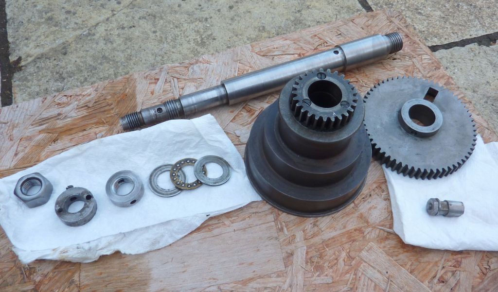
The knurled collar is just for keeping the change gear in place. Starting from the rear face of the bearing on the back end of the spindle there should be…
1. End float adjustment collar (screwed onto the spindle)
2. change gear drive collar (slides on and is secured with a grub screw)
3. the first change wheel (slides on and is secured by pegs engaging with the drive collar)
4. the knurled collar (screwed onto the spindle)Number 1 is for adjusting the end float. this collar has a hole to take the adjuster – the proper tool for this is a 'C' spanner… which I confess that I don't have.
Here is a photo of my spindle when I had it apart. The change gear is not in the pic. On the left you can see the three collars (but I had a nut instead of the correct knurled collar at this time). Inboard of the tail bearing you should have a thrust ball race which consists of the cage and two washer-like things. Then comes small backgear/cone pulley assembly and then the bull gear with its engagement peg before you get to the spindle nose bearing.
Sounds like your spindle taper is fine… and a good fit for MT1 which is useful info thanks. Centres should lock into the taper if all is as it should be. Yes you should use a bit of bar through the spindle to tap things out of the taper from behind otherwise you will never shift them. I have a bit of 1/4 brass bar for this, but you could go up to 3/8 and it would still fit.
Regards, Andy
9 June 2020 at 10:09 #478652Jacob Leonidou
Participant@jacobleonidou84012It's curious to say the least. It was the reason i thought my lathe was chattering at first, turns out it was just inexperience.
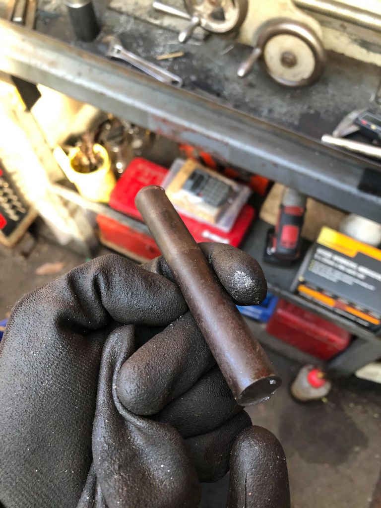
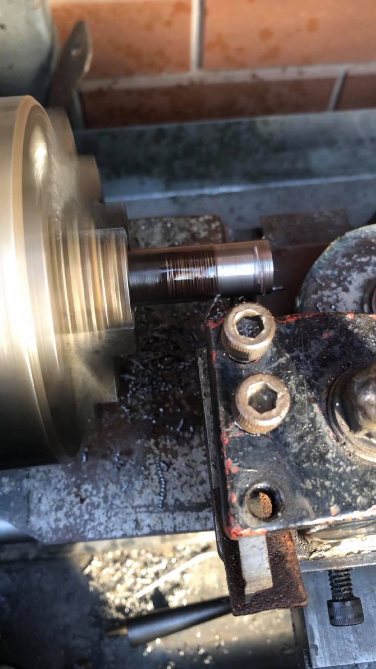
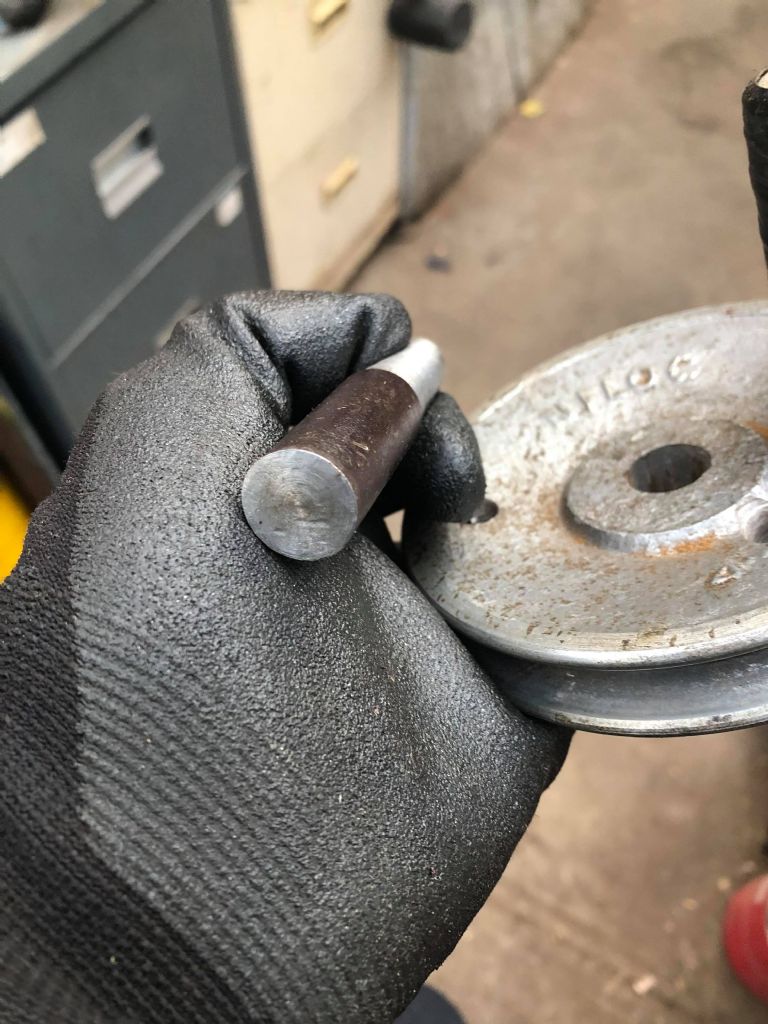
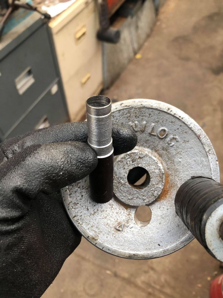
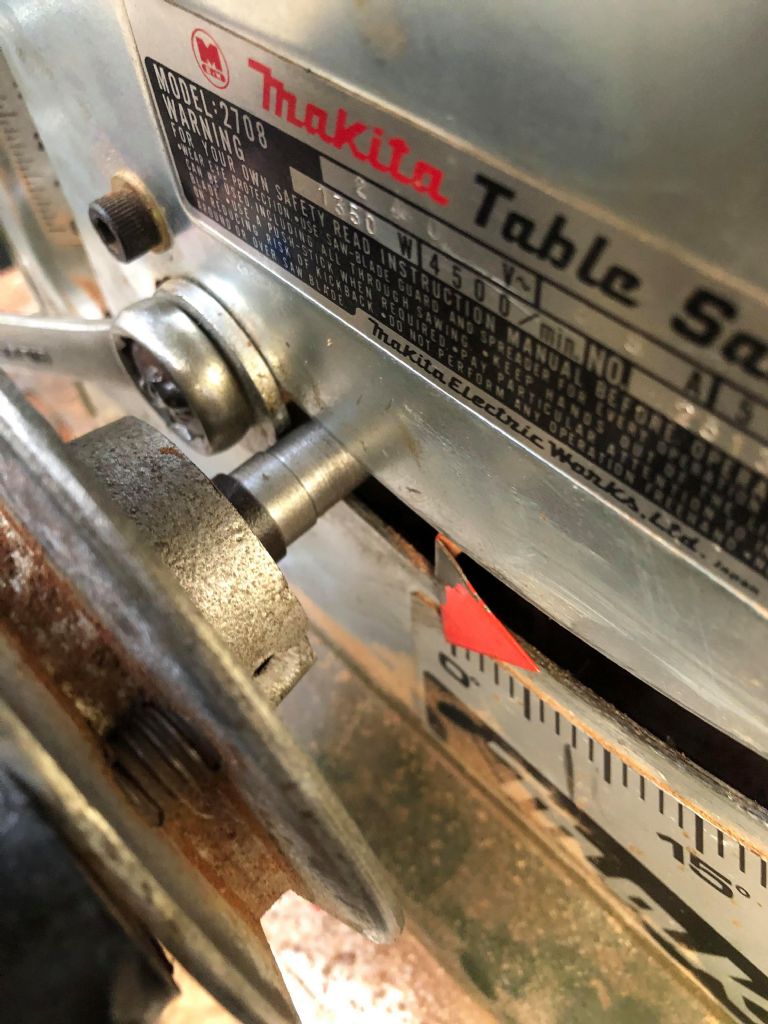
So today i am proud to announce that i made my first proper chips, thanks to the help i received from you both. I decided to make a shaft to convert the adjusting mechanism on my table saw from 'winding door knob' to 'handwheel'. I started with some 16mm round stock and turned down half of it to the required OD. I then drilled the inside to the required ID. Unfortunately i got too close to the OD when drilling and warped a third of the part. By this time i was probably 3 hours in so i quickly roughed out the rest of the part and drilled a hole with a bit more meat to spare. Worked really well and i am really happy overall. Up until this point i was unable to do anything with the lathe but today was the first time i felt like a machinist albeit an inexperienced one.
Ignore the poor surface finish as i was in a hurry having wasted a lot of time already. Ill probably go back and touch it up. Point being it didn't chatter and i was left with proper turning marks! The first time i ever tried, the finish was so poor i thought the lathe was broken. Despite the bearing play it still works well which is a big relief. I know that if worst come to worst i can make new bearings but this would require a bit more experience than what i currently possess. Especially so considering i don't have information on the factory specs for the bearings.
The only significant problem i had was with the tailstock. It needs adjusting and had a tendency to wobble the drillbit, especially the centre drill. I found that the MT1 taper didn't really lock in nicely as it spun with the bigger drill bit in the Jacob's chuck more than once. I couldn't seem to get it locked in nicely. I attempted to adjust the tailstock as best as possible by loosening the centre bolt but it was all by eye. I think the wobble is what warped the part initially once i turned it down thin enough to be a bit malleable.
As for the picture you posted Ill have a look at mine and compare. It helps me better understand the machine and what makes it work.
All in all i know it works and i am very happy!
9 June 2020 at 19:07 #478750Andy Carlson
Participant@andycarlson18141That's great news Jake, glad you have got some useful work out of your machine.
Check your tailstock taper for scoring and get hold of an MT1 finishing reamer if that is the problem. Also check the taper on your chuck. If it has any 'dings' or scoring lines then take a stone to them by hand – you need to take the raised bits off and just leave the hollows.
The quick way to get the tailstock aligned is to put a dead centre in the headstock and tailstock and bring them together trapping a ruler or a bit of metal strip of similar thickness in between. If the strip skews left/right or up/down then you know which way the alignment is off. Left/right is easy as you have seen. For up/down you will need to put some shims between the main tailstock casting and the base.
The saddle/cross slide gets in the way when you are doing this job. You don't really want the barrel extended too far. My tailstock securing nut (the one that clamps it to the bed) has a tommy bar 'handle' screwed in. If you can get the tommy bar unscrewed (it may not play ball) then you can fully undo the securing nut, take the tailstock off and mount it on bed between the saddle and the headstock.
Even with the alignment perfect you will probably find that the barrel droops when extended. The barrel clamp helps but it still happens.
Regards, Andy
9 June 2020 at 20:08 #478765Brian Morehen
Participant@brianmorehen85290Hi Jake.
Looks good just give youself time you learn slower when you take time dont take one heavy cut i much prefer 3 cuts 2 nearly there and the last one correct, I have no free end play in my spindle perhaps you need another shim or to tighten the spindle nut a bit more . I have a bar that fits into my chuck with the tailstock end turned to fit , there are a number of way to align the lathe chuck centre and tailstock , One a ground steel bar centre each end , And a dial gauge held in the cross slide moved along the bar will show up any misalinement.you can hold the bar in your chuck or use a morse taper each end. or use a set of chuck soft jaws which have been bored to the correct size for the bar you are useing this way you know chuck centre is correct,
Well done Good Luck Brian
-
AuthorPosts
- Please log in to reply to this topic. Registering is free and easy using the links on the menu at the top of this page.
Latest Replies
Home › Forums › Manual machine tools › Topics
-
- Topic
- Voices
- Posts
- Last Post
-
-
smokeless cutting oil
Started by:
Chris12 in: General Questions
- 6
- 6
-
27 July 2025 at 07:06
 JasonB
-
Model Engine running just off a naked flame
1
2
Started by:
 Blue Heeler
in: Stationary engines
- 10
- 35
-
27 July 2025 at 07:00
 JasonB
-
Clock gear cutting needed or advice in setting up from scratch.
Started by:
mccormackclockrepairs in: Introduce Yourself – New members start here!
- 3
- 4
-
27 July 2025 at 00:44
mccormackclockrepairs
-
Plain bearing speeds
Started by:
zytoooh in: General Questions
- 11
- 13
-
26 July 2025 at 22:44
Nigel Graham 2
-
Foru-Way Toolpost Question
Started by:
Nigel Graham 2 in: Workshop Tools and Tooling
- 6
- 15
-
26 July 2025 at 22:04
Nigel Graham 2
-
Simple chuck/faceplate threaded mount for mill table
Started by:
Peter Cook 6 in: Workshop Tools and Tooling
- 4
- 5
-
26 July 2025 at 21:41
Nigel Graham 2
-
Amadeal lathes – Any good??
1
2
Started by:
Tim Sallows in: Workshop Tools and Tooling
- 17
- 33
-
26 July 2025 at 21:21
Bill Phinn
-
Boxford STS 10 30 weights
Started by:
PutneyChap in: Manual machine tools
- 4
- 6
-
26 July 2025 at 20:04
Mark Hall
-
Recycling UK
Started by:
Speedy Builder5 in: The Tea Room
- 11
- 12
-
26 July 2025 at 19:27
noel shelley
-
Bridgeport ways and wear
Started by:
inline in: Manual machine tools
- 8
- 19
-
26 July 2025 at 17:53
ryan.carter848
-
Lathe index tips
Started by:
petro1head in: General Questions
- 9
- 21
-
26 July 2025 at 13:16
 JasonB
-
John Wilding turret clock escapement wheel
Started by:
Andy Freeman 1 in: Clocks and Scientific Instruments
- 2
- 3
-
26 July 2025 at 10:27
bernard towers
-
Reel repair
Started by:
Andy Sproule in: General Questions
- 8
- 10
-
26 July 2025 at 10:20
Andy Sproule
-
Arc Euro Trade Ltd.
1
2
3
Started by:
Ketan Swali in: General Questions
- 46
- 52
-
26 July 2025 at 09:57
Ketan Swali
-
Track my loco.
Started by:
Thomas Clarke in: General Questions
- 10
- 13
-
26 July 2025 at 09:35
Speedy Builder5
-
Calculation the deflection of a box section steel beam supported at each end
Started by:
Greensands in: Help and Assistance! (Offered or Wanted)
- 7
- 9
-
26 July 2025 at 08:42
 Nicholas Farr
-
Adcock And Shipley vertical milling head – worth anything?
Started by:
ell81 in: General Questions
- 3
- 3
-
25 July 2025 at 23:25
 Bazyle
-
Round Bar Bender
Started by:
Trevor Howley in: Workshop Tools and Tooling
- 8
- 18
-
25 July 2025 at 20:16
Trevor Howley
-
Electroplating questions
Started by:
Baldric in: Help and Assistance! (Offered or Wanted)
- 4
- 6
-
25 July 2025 at 19:33
bernard towers
-
Instrument/DTI repair
Started by:
Lee Reynolds 1 in: Help and Assistance! (Offered or Wanted)
- 6
- 11
-
25 July 2025 at 19:23
Dave S
-
7MM Diameter Drills
Started by:
 KEITH BEAUMONT
in: The Tea Room
- 11
- 18
-
25 July 2025 at 18:31
Howard Lewis
-
Got some gear and some idea!
Started by:
zytoooh in: Introduce Yourself – New members start here!
- 8
- 15
-
25 July 2025 at 17:47
Charles Lamont
-
Yet another scam
Started by:
 Dell
in: The Tea Room
- 6
- 7
-
25 July 2025 at 13:22
Nigel Graham 2
-
Colchester Master Mk1 lifting + moving advice
1
2
Started by:
choochoo_baloo in: Manual machine tools
- 17
- 40
-
25 July 2025 at 12:00
Mark Hall
-
My vise isn’t at 90 degrees
1
2
Started by:
moonman in: Beginners questions
- 18
- 30
-
25 July 2025 at 11:51
 Bazyle
-
smokeless cutting oil
-
Latest Issue
Newsletter Sign-up
Latest Replies
- smokeless cutting oil
- Model Engine running just off a naked flame
- Clock gear cutting needed or advice in setting up from scratch.
- Plain bearing speeds
- Foru-Way Toolpost Question
- Simple chuck/faceplate threaded mount for mill table
- Amadeal lathes – Any good??
- Boxford STS 10 30 weights
- Recycling UK
- Bridgeport ways and wear


