Advice on lathe Threading tools

Advert

Advice on lathe Threading tools

Home Forums Workshop Tools and Tooling Advice on lathe Threading tools

Viewing 25 posts - 51 through 75 (of 87 total)
  • Author
    Posts
  • #474008
    SillyOldDuffer
    Moderator
      @sillyoldduffer

      Posted by Jim Beagley on 22/05/2020 17:23:00:

      Any clever solutions for knocking up a manual winding handle?

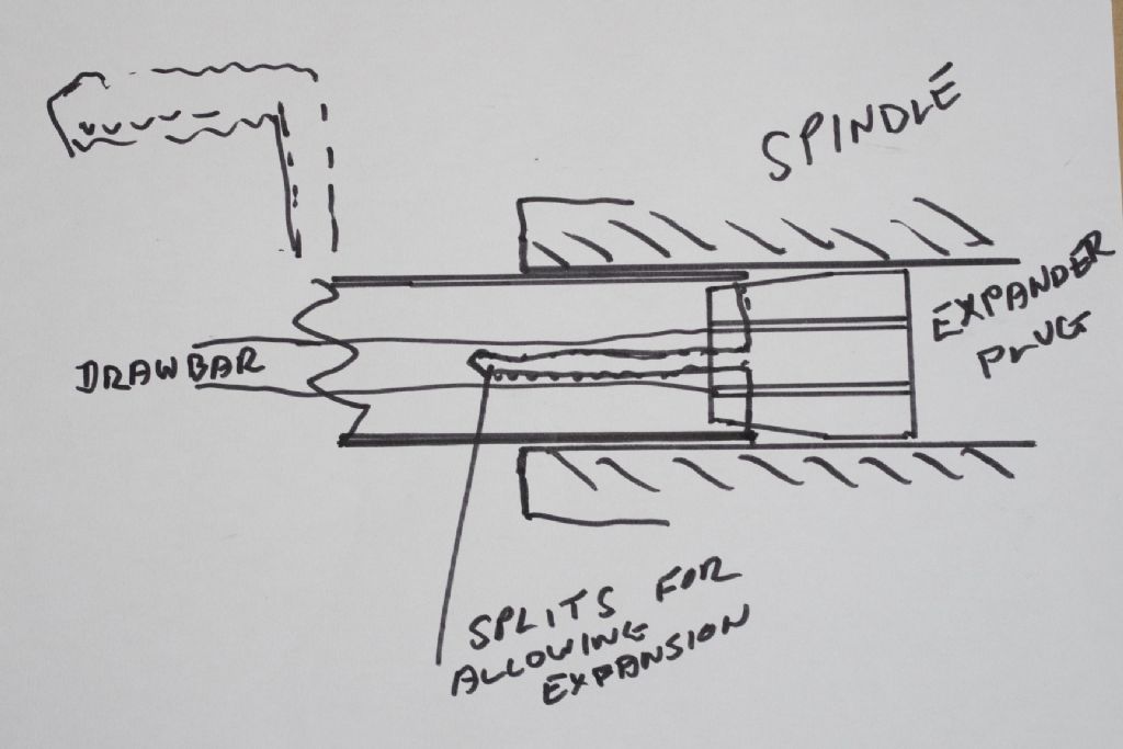
      Can't find a picture unfortunately but I made one for my mini-lathe based on the mechanism used to adjust bicycle handlebars.

      Turn about 75mm of aluminium rod so the diameter just fits in the spindle. Drill a 9 or 10mm hole through the rod to comfortably pass a long M8 bolt. Then saw the rod at a 45 degree angle across the middle and fix a crank handle to one of the pair.

      No need for any precision.

      Assemble so the head of the bolt is inside the spindle and supported by a large washer on the flat end. With the bolt loose, insert the two parts into the spindle and tighten the nut. Tightening causes the two angled surfaces to slide and expand to grip the inside of the spindle. Undoing the nut releases the grip allowing the winder to be removed.

      Dave

      Advert
      #474013
      Martin Connelly
      Participant
        @martinconnelly55370

        What is the slowest speed on your lathe? Mine is nominally 66 rpm which is close to 1 rev per second. If you have a lower slowest speed then it should be possible to use power for threading. One thing to be wary of with a manual winding handle is that if you are using carbide tooling then any reverse rotation of the spindle with the tool in contact with the workpiece runs the risk of breaking the carbide. It's great in compression being pushed down onto its seat but hopeless in tension which applies when the tip is pushed away from its seat.

        Martin C

        #474022
        old mart
        Participant
          @oldmart

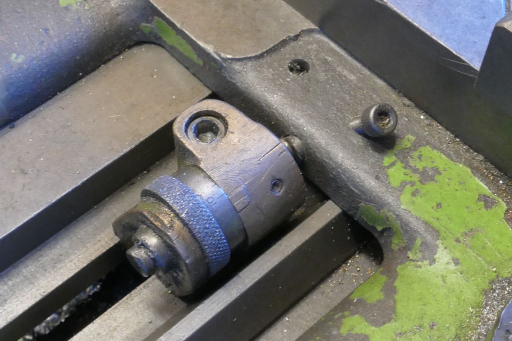
          The winding handle I made to do the first 1 3/4 8 W backing plate thread was super crude. Whatever materials came to hand. The end in the spindle had a simple expander and the winding handle was just a bit of scrap iron, nothing like those very nice Myford winders.

          _igp2598.jpg

          #474035
          old mart
          Participant
            @oldmart

            As mentioned by Martin Connelly, you must back off the tooling each time you reverse to the start point. Earlier I mentioned zeroing the cross slide dial before starting. Because this is a bore you are threading after practicing on external threads, you should just touch the bore first and then dial in the total depth of cut expected (0.080&quot. Remember, you are cutting backwards like when boring. So you should return each time to 80, or a bit more or the insert will probably break. Having the intended cuts written on a sheet of paper and crossing them off as you go is a help also. So the cuts would be as follows:
            80, 68, 58, 48, 40, 32, 25, 19, 14, 10, 7, 5, 4, 3, 2, 1 until the first marks show on the register.

            By hand has another advantage, it will be obvious when you run off the end of the thread at each cut. You will feel and probably hear the cut in progress, and if you count the turns from first contact to running out of thread, you can then reverse a couple of turns more backing out. This will take care of any backlash when going into the cut.

            Making a practice dummy out of aluminium first before committing to the backplate would be a good idea, but you must use AC90, or WD40 to lubricate it when you are machining it. And it should be set in the chuck with the same gap between it and the face of the chuck as the real thing would have.

            #474058
            John Baron
            Participant
              @johnbaron31275

              Hi Guys,

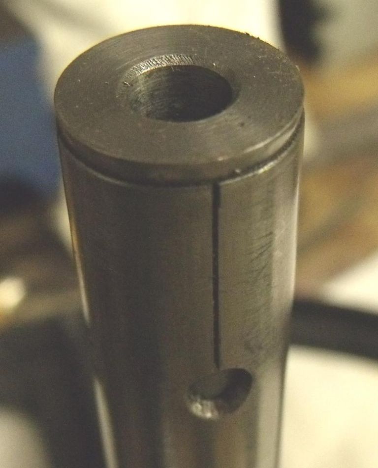
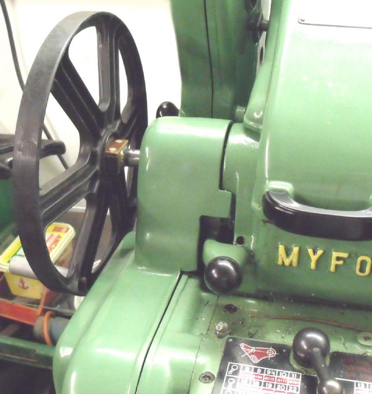
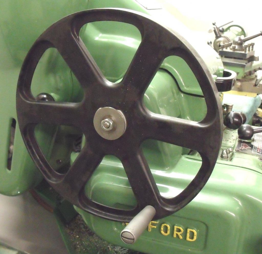
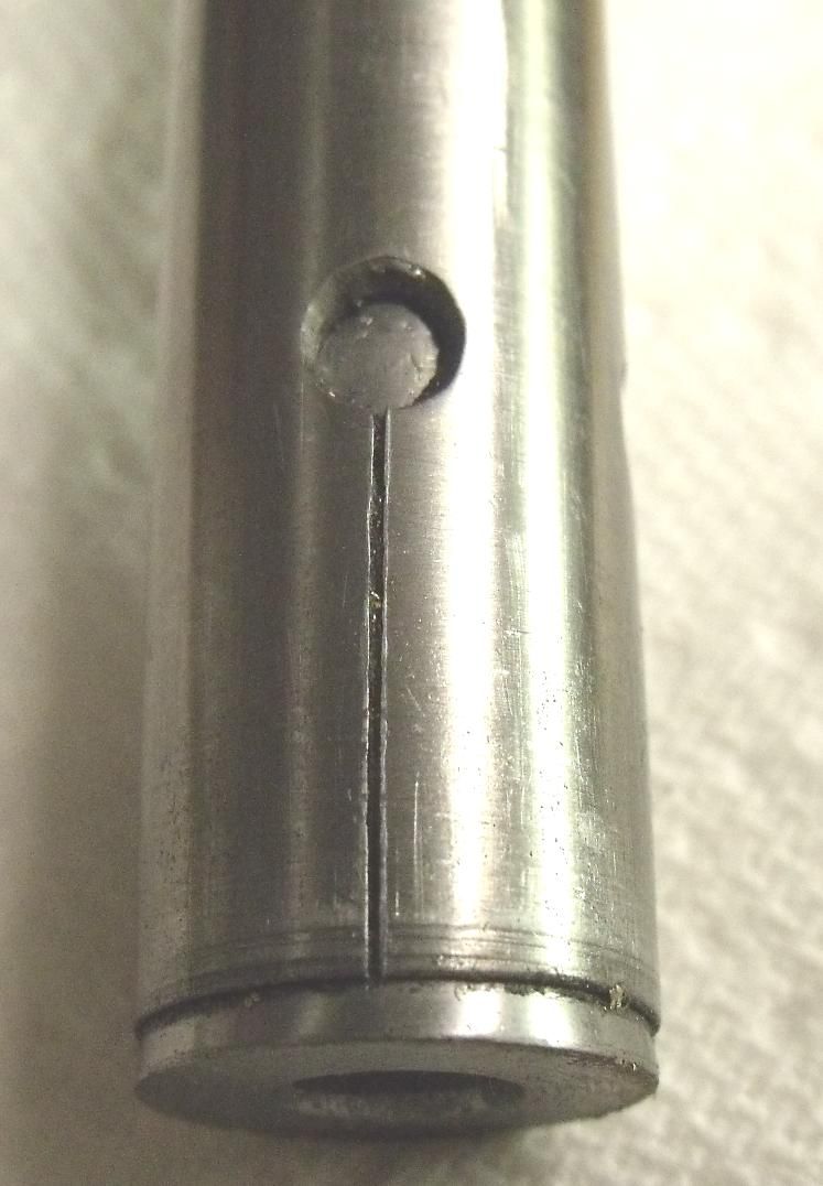
              I made my lathe winding handle from a scrap plastic drum pulley from a old front loading washing machine. I made a revolving handle and screwed it into one of the spokes to make it easy to turn.

              The collet is similar to the one in the drawing above.

              21022015-00.jpg

              21022015-01.jpg

              21022015-03.jpg

              21022015-05.jpg

              There are other pictures in my album.

              #474062
              old mart
              Participant
                @oldmart

                That handle will make all the other Myford people green with envy. You will never get me to post a photo of the one I made.

                #474063
                John Baron
                Participant
                  @johnbaron31275
                  Posted by old mart on 22/05/2020 20:52:12:

                  That handle will make all the other Myford people green with envy. You will never get me to post a photo of the one I made.

                  Oh go on ! It can't be that bad if you still have and use it.

                  That wheel came from a scrap yard just for the price of taking a bolt out of the hub and I kept the belt. Handy keeping a mover in the boot.

                  #474230
                  old mart
                  Participant
                    @oldmart

                    Myford gears are a coarser pitch than S&B ones. A shame as they are plentiful.

                    There is info available from lathes UK on the Sabel:

                    https://store.lathes.co.uk/print/ms580c

                    Edited By old mart on 23/05/2020 14:43:21

                    #474326
                    old mart
                    Participant
                      @oldmart

                      One thing I forgot to mention is that while you are winding the spindle by hand, is to keep the leadscrew nuts engaged throughout. Reversing the spindle at the end of each cut will automatically move the saddle to the starting position. It doesn't matter how far you go back, but two extra turns will take care of any backlash in the gearing.

                      #474881
                      Jim Beagley
                      Participant
                        @jimbeagley46363

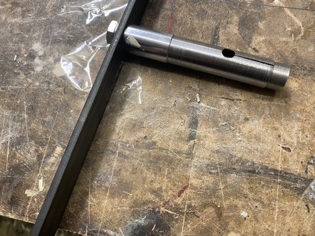
                        None of the backplate stuff arrived for the weekend to I made a spindle handle instead. Thanks for the inspiration.
                        7717201e-8a62-4662-84f4-66c97761438f.jpeg

                        #474887
                        John Baron
                        Participant
                          @johnbaron31275

                          Hi Jim, Guys,

                          Not bad, not bad at all ! I've seen far worse.

                          I put a collar on mine to stop the winding wheel from fouling the change gear cover. You can't see it in my pictures above. But it was too easy to put the handle in and then find that you couldn't turn the handle because it was pressed up against the cover.

                          #475131
                          old mart
                          Participant
                            @oldmart

                            The joint between the handle and the shaft needs to be strong because of the force needed to cut these large threads.

                            #475219
                            Jim Beagley
                            Participant
                              @jimbeagley46363
                              Posted by old mart on 26/05/2020 16:46:53:

                              The joint between the handle and the shaft needs to be strong because of the force needed to cut these large threads.

                              I’ve not finalised the handle arrangement yet but I’ll take note of your comment.
                              The tube has a bush at the handle end that will probably get welded in somehow and attached to the handle.

                              Got the threading tools today so looking forward to making a mess of the floor

                              #475444
                              Jim Beagley
                              Participant
                                @jimbeagley46363

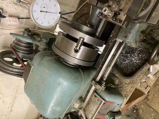
                                Well the Boxford backplate has arrived and it fits in my 4-jaw.
                                All dialled in, plus I’ve got the BSW insert.
                                So I’m guess the first step is to completely bore out to the ID to start the thread from, and the afterwards counterbore the boss for the spindle clearance?

                                jeez this is nerve wracking!

                                fbdd15a3-fcd1-48e7-97ab-c3b3144ce18c.jpeg

                                #475741
                                Jim Beagley
                                Participant
                                  @jimbeagley46363
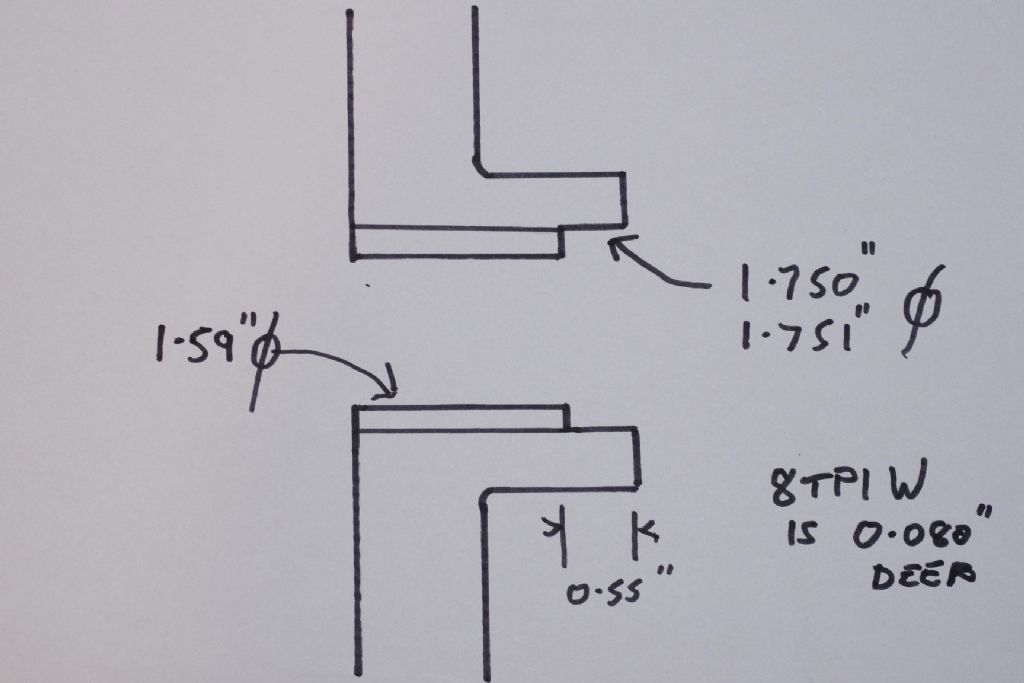
                                  Posted by old mart on 19/05/2020 21:25:27:

                                  I expect a damaged tap with a 8 tpi thread would be as rare as hens teeth. I have made a sketch of the thread which shows the main dimensions. The starting bore of the thread is not critical, it could range between 1.59" and 1.614". I have always gone for the smaller size using carbide inserts. The size is right when the first sign of the thread shows in the 1.75" register. It would take multiple passes from just touching the bore to be threaded. The register size needs to be no less than 0.001" greater than the measured spindle size, or it will be very difficult to screw the plate on.

                                  I would go 12,10,10,8,8,7,6,5,4,3,2, and 1 in thousandths of an inch, keeping an eye out when close to the end for the witness mark on the register.

                                  _igp2595.jpg

                                  Edited By old mart on 19/05/2020 21:31:08

                                  Hey Old Mart.
                                  I have started with this process and bored the plate to 1.59D.
                                  How critical is your measurement shown of the 0.55 depth of the 1.75D counterbore?
                                  I have measured the plates I have, and the original S&B one is deeper than that by some amount.

                                  Can I simply cut it to 0.55 then at the end of the procedure just extend the counterbore till the plate screws up to the face of the spindle?

                                  cheers, Jim

                                  #475749
                                  Martin Connelly
                                  Participant
                                    @martinconnelly55370

                                    You could screw cut the whole thread first then counterbore but that just means more thread to cut. I think the best thing to do is match what you have already since you know it works.

                                    Martin C

                                    #475752
                                    Jim Beagley
                                    Participant
                                      @jimbeagley46363

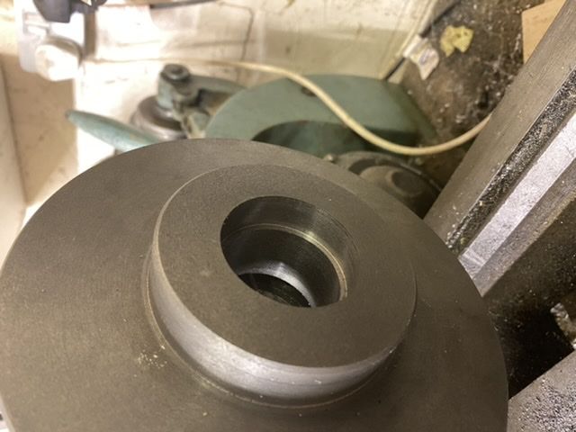
                                      Well I’ve cut the bore and counterbore to Old Marts numbers. I’m strictly metric so there was some calculator action going on!

                                      Tomorrow I’m going to attempt the threading

                                      Boring Complete

                                      #475949
                                      Jim Beagley
                                      Participant
                                        @jimbeagley46363

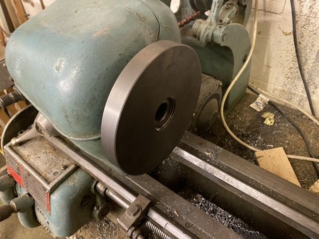
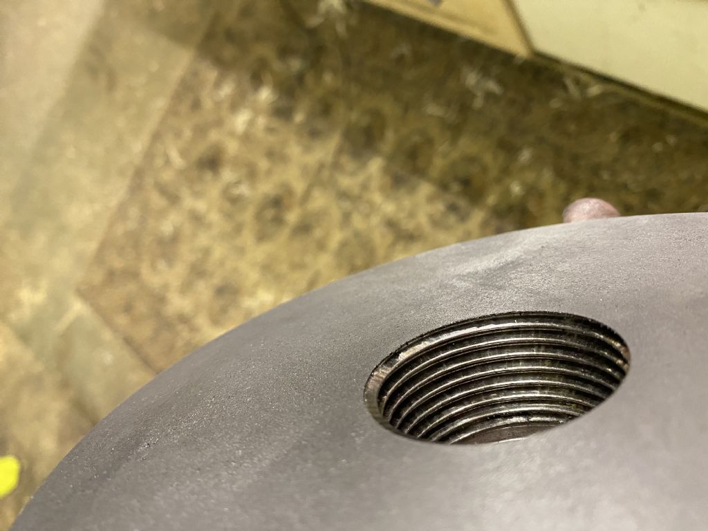
                                        b37e7594-db83-4623-afe9-ecc72dcdf81c.jpegSuccess. That’s all for now, but it wasn’t plain sailing so I will have some questions in the morning.
                                        but mainly, it’s done! Yay

                                        5907262b-796a-46ec-a530-0f1331f81802.jpeg

                                        #476122
                                        old mart
                                        Participant
                                          @oldmart

                                          Now you have it screwed on to the spindle, it needs bedding in a bit. Make sure every bit of swarf is removed from the internal thread using a small wire brush. Also deburr the ends of the thread, a Dremel comes in useful here if you have one. Clean and oil the threads and with lowest back gear engaged, screw the plate on and off several times, fairly tight. Use a strap wrench to start it unscrewing. The plate must come into contact with the face of the spindle, if it gets tight before contact is made, you will have to cut back the threads a little adjacent to the 1.75 register in the plate.

                                          A light facing cut or two will ensure the plate is true to the spindle axis.

                                          Edited By old mart on 30/05/2020 15:09:19

                                          #476768
                                          Jim Beagley
                                          Participant
                                            @jimbeagley46363

                                            So I wonder if I can air some of the problems I had to see if I can find out where I went wrong.

                                            When the thread started to show on the counter-bore, the thread cut registered on the outermost edge of the boss (nearest the spindle in fitment) but didn't run along the full length of the counter-bore, which at the time I didn't understand.

                                            I stopped at this point and reversed the plate and chuck, and the thread would start but go hardly any distance onto the spindle, so I reset, cut the thread a thou deeper and tried the fit again.
                                            This went on for ages, with my trying to get the thread to show the full length of the counter-bore, and trying the plate on the spindle. With every pass, the thread would engage very slightly more, but nowhere near fully.

                                            Eventually, I gave up this method and took a tiny cut off the counter-bore face and the plate screwed on instantly.

                                            So but conclusion after all that is that maybe the counter-bore was slightly tapered?
                                            Now I used the compound slide to machine the counter-bore, as its got a dial, whereas the carriage doesnt.
                                            Is this a boo boo, as its the only way I can think that I could have got the taper.
                                            In hindsight I realise I could have used the DTI to get the depth of cut from the carriage.

                                            So, sorry for the long post, but its complicated (to me anyhow).
                                            Anyone got any thoughts on that lot?
                                            I've got another Boxford 1-1/2 plate to have another go but it'd be better to get it less wrong 2nd time around.

                                            Cheers,
                                            Jim


                                            Edited By Jim Beagley on 01/06/2020 18:36:03

                                            Edited By Jim Beagley on 01/06/2020 18:36:40

                                            Edited By Jim Beagley on 01/06/2020 18:37:00

                                            Edited By Jim Beagley on 01/06/2020 18:37:54

                                            #476782
                                            Martin Connelly
                                            Participant
                                              @martinconnelly55370

                                              You should have used the carriage to cut the register without a taper. You can use the compound slide to set the depth and use a stop for the carriage to do this. Some Smart and Brown lathes have a positionable stop that fits between the ways, there is a small hard point on the leading and trailing faces of the carriage that contacts it. If you don't have one then a simple stop can be made to grip the nearside dovetail to act as a carriage stop.

                                              Position the stop, move the carriage up to the stop. Set the compound slide dials to zero with the tool just contacting the face of the workpiece. Wind the carriage away from the work piece and advance the compound the required depth.

                                              Now when the carriage is taken up to the stop the tool goes the correct distance into the bore.

                                              You can use the compound to do the job but it must be set to exactly parallel to the ways using a dti and suitable test bar.

                                              Slight errors in the compound angle away from perfectly parallel to the ways will not cause issues setting the depth (cos of a small angle is very close to 1) but will cause tapering of the bore produced.

                                              Martin C

                                              p1150201.jpg

                                              The Model M has a clutch so you can power up to the stop without damaging the lathe.

                                              Edited By Martin Connelly on 01/06/2020 19:27:21

                                              #476807
                                              Jim Beagley
                                              Participant
                                                @jimbeagley46363

                                                Hi Martin.
                                                That all makes perfect sense.

                                                I have a stop and did exactly as you suggested and now have a perfect counterbore using the carriage.
                                                Its so so simple when someone tells you what to do but it seems insurmountable beforehand.
                                                My apron has a clutch but I have not used it except to adjust it to engage the apron or cross slide.
                                                I seem to have a slight fear of breaking it!

                                                OK so now to cut the thread again and see how it works this time.
                                                I really do appreciate all the time you guys are taking to answer my questions.

                                                Thanks

                                                #476817
                                                old mart
                                                Participant
                                                  @oldmart

                                                  Don't worry, the plate will be perfectly ok. You now know that lining up the degrees to zero on the compound doesn't mean much. It is possible to get the compound parallel to the spindle axis, but its a lot of bother.

                                                  I know that your plate will be perfectly usable as we have a large quantity of faceplates and chucks at the museum. The supposedly best backplate I made has a register with 0.0005" clearance on the spindle. It is a pain to screw on and off. The loosest one has at least 0.020" clearance, it is easy to fit. They both repeat perfectly each time they are fitted. Remember what I said about screwing the plate on and off a few times before final machining of the front face.

                                                  The next time you make a backplate, you will make one with greater accuracy, but in the real world, it won't work any better than your Mk 1.

                                                  This is one of the rare times that you can get away with these errors, most other threading jobs will not be so forgiving.

                                                  #476828
                                                  Jim Beagley
                                                  Participant
                                                    @jimbeagley46363

                                                    Thanks Old Mart; that’s good to hear.

                                                    I am both learning how to use the machine and learning how to do a task. But it’s good learning especially getting good advice.
                                                    I was wondering if it was possible to replace the scale on my cross slide as it’s barely legible, but maybe it’s not worth it?

                                                    i only have a set or digital verniers at the moment. Is it worth me getting some internal gauges and a micrometer?
                                                    My immediate goal is the make a Stuart S50.

                                                    Jim

                                                    PS- which museum?

                                                    #476837
                                                    Martin Connelly
                                                    Participant
                                                      @martinconnelly55370

                                                      I don't use digital calipers (they are not verniers), I tried but could not get sufficiently repeatable readings because every time I tried to hold the reading or clamp the screw they moved and trying to read them in situ was hard work. I have a couple of mechanical vernier calipers with a coarse clamp screw and thumbwheel like the type shown in this link.

                                                      Workshop Technology Blog

                                                      A micrometer is useful for as well and allows you to keep the calipers for general use and keep the micrometer in good condition for when accurate jobs require it.

                                                      Bore gauges are probably something that can wait. Usual method for model engines is bore a parallel, round and smooth cylinder and then machine the piston to match the cylinder. The actual diameter is not usually critical. You can make go/no go gauges for a lot of jobs if you have a good micrometer.

                                                      Martin C

                                                    Viewing 25 posts - 51 through 75 (of 87 total)
                                                    • Please log in to reply to this topic. Registering is free and easy using the links on the menu at the top of this page.

                                                    Advert

                                                    Latest Replies

                                                    Viewing 25 topics - 1 through 25 (of 25 total)
                                                    Viewing 25 topics - 1 through 25 (of 25 total)

                                                    View full reply list.

                                                    Advert

                                                    Newsletter Sign-up