3 phase inverter query?

Advert

3 phase inverter query?

Home Forums General Questions 3 phase inverter query?

Viewing 25 posts - 26 through 50 (of 52 total)
  • Author
    Posts
  • #324909
    Emgee
    Participant
      @emgee
      Mark also posted on the 26th:

      'Unfortunately, mid-afternoon the pendant for the electric auxiliary hoist managed to weld all of its switch contacts together (Up and Down). This lead to a release of magic smoke into the environment and a certain amount of bad language.'

      There should be electrical and mechanical interlocks on hoist circuits to prevent both contactors energising at the same time, it is wise to at least have electrical interlock as a minimum on any reversing type application.

      Emgee

      Advert
      #324912
      Absolute Beginner
      Participant
        @absolutebeginner

        Andrew, your reasoning and thoughts are correct. there is no reason why a plug and play inventor cannot be used "in a ring main scenario" as long as the total load does not exceed the inverters capabilities, i.e total load.

        The only thing you have to consider is the initial inrush correct when switching on machines

        Gary

        #324913
        Absolute Beginner
        Participant
          @absolutebeginner

          Sorry inrush Current

          #324915
          Michael Briggs
          Participant
            @michaelbriggs82422

            +1 Andrew, it is disconnection that is the problem.

            #324928
            Mark Rand
            Participant
              @markrand96270
              Posted by SillyOldDuffer on 01/11/2017 22:17:37:

              Posted by Mark Rand on 01/11/2017 21:50:11:

              [RANT MODE]


              If the manual specifically states that downstream switching is not allowed then that's one thing.


              If the VFD was designed in the last 20 years using IGBT output stages with output current monitoring, instead of GTO thyristors without, it'll be quite happy with downstream switching. It's as simple as that. What do you think all the computer UPSs, camper-van 240V power supplies, grid-tied inverters on solar panels and inverter welding sets are, if not fixed frequency inverters which can cope with downstream switching?

              In the meantime, I'll just carry on running my workshop with its half a dozen 3ph motors from the single VFD on the other end of the 3ph sockets around the walls.


              [/RANT MODE]

              Edited By Mark Rand on 01/11/2017 21:50:57

              Edited By Mark Rand on 01/11/2017 22:03:36

              Edited By Mark Rand on 01/11/2017 22:04:21

              Mark also posted on the 26th:

              'Unfortunately, mid-afternoon the pendant for the electric auxiliary hoist managed to weld all of its switch contacts together (Up and Down). This lead to a release of magic smoke into the environment and a certain amount of bad language.'

              smiley


              Yup. That was a cheap 500W single phase, Chinee hoist bought from Lidl (Switch replaced by next day delivery of a better unit from cpc.farnell.com). The VFD is a 23kVA Danfoss VLT series unit.


              Disconnection is no problem at all for any modern VFD. The potential reflected transient voltages seen at the VFD output in normal running are as great as those that could be caused by disconnection. This is why the IGBTs have integral freewheel diodes to cope with that problem.

              The C-E voltage is limited by the DC bus voltage and the flywheel diodes.

              Edited By Mark Rand on 02/11/2017 01:11:01

              #324930
              Mark Rand
              Participant
                @markrand96270
                Posted by Emgee on 01/11/2017 22:38:11:

                Mark also posted on the 26th:

                'Unfortunately, mid-afternoon the pendant for the electric auxiliary hoist managed to weld all of its switch contacts together (Up and Down). This lead to a release of magic smoke into the environment and a certain amount of bad language.'

                There should be electrical and mechanical interlocks on hoist circuits to prevent both contactors energising at the same time, it is wise to at least have electrical interlock as a minimum on any reversing type application.

                Emgee

                Having held the plastic 240V pendant of a 250kg hoist in my shed with smoke coming out of it. I agree fully.

                On the other hand, it was slightly less scary than the occasion when someone had removed the screws holding the metal 415V pendant together on the little 10 ton crane was using at work, I was left holding the back half with one hand and gingerly poking at the buttons with the other.

                Luckily, no machine tools were harmed in either case cheeky.

                #324941
                Michael Briggs
                Participant
                  @michaelbriggs82422

                  Allen Bradley, Mitsubishi and IMO all state that a motor should only be disconnected from the drive output when the motor is at a standstill. That is NOT an exhaustive list, just a 10 minute search. If you need to switch the drive output, read the manual or contact the manufacturer.

                  #324943
                  not done it yet
                  Participant
                    @notdoneityet

                    If you need to switch the drive output, read the manual or contact the manufacturer.

                    Same as I posted earlier. I cannot see any advantage of posting an enquiry on the forum rather than asking the manufacturer or supplier. It is clear that a 23.5kW inverter is of industrial grade. That may not be the same as a tiddly hobby inverter which may just manage 2KW.

                    The make and model of this particular inverter has not been disclosed. I am now wondering why that is. Nobody, other than the OP, has a real handle on the actual quality or specs of the inverter concerned.

                    The rant above might indicate only switching around 15% of the capacity at any one time (may be a bit more but is indeterminate, other than being less than 4kW, for the current audience). A little different than switching off, perhaps 75% or more of the normal full current load.

                    I would expect the small motor being switched, while the larger ones are running, presents little problem. But I don't know for sure. No more than switching the larger motors, to be honest.

                    As for our absolute beginner, there should be no problem of starting via a switch (apart from no ramp control, so maximum inrush current). That is not the issue here – it is breaking the circuit, under load conditions, which is the questionable operation. Clearly some instructions/manuals emphasise the 'no switching' aspect, so either the OP needs to carefully read the instruction manual or consult someone who knows for sure regarding that particular item. As I said 3arlier, I would want confirmation in writing – too many verbal conversations are conveniently forgotten or repudiated.

                    #324958
                    SillyOldDuffer
                    Moderator
                      @sillyoldduffer

                      Agree with Michael, NDIY and others. Unless you don't mind taking risks much better to check specifications if you can. Anyone else done the course where 'Assume' is defined as 'to make an Ass of you and me'?

                      One risk not mentioned is the wider effect of live switching – the effect of voltage spikes on whatever else happens to be connected. A VFD with beefy modern IGBTs might be immune to spikes, but can you say the same about the insulation of your motors? 3-phase synthesised by a simple pulse device is much more likely to generate voltage spikes than real 3-phase from an alternator. You may be applying the equivalent of a severe 'Megger' test to your whole workshop every time a motor is switched off…

                      Joe Noci's post made a lot of sense to me; following his advice is unlikely to cause trouble. The problem with Mark's "rant" is the number of unknowns in it:

                      • IF the manual doesn't explicitly forbid downstream switching, AND
                      • IF the VFD was designed in the last 20 years, AND
                      • IF the VFD has IGBT output stages, AND
                      • IF the VFD output stages have Current Monitoring

                      Dave

                      #324966
                      Andrew Tinsley
                      Participant
                        @andrewtinsley63637

                        Hello,

                        This seems to have caused some "discussion"! The inverter that I am talking about is an ABB unit. It was used in a small air conditioning system. Unfortunately I can't find the model type, I suspect the adhesive label with the details has come adrift (there is a sticky oblong patch on the inverter, where I think it might have been). Closer inspection of the remaining label says that it is rated at 2,2 kW (not 2.0kW as I first stated). Now if this is input or output power I don't know. It is obviously an industrial unit and built like a tank, so not a tiddly hobby unit! I suppose I could try and browse through any published ABB information to see if I can find the model

                        There were two of these units being replaced, so I may well see if the other is still available. If so I will buy it and test it to destruction or not as the case might be. I would usually try and find the manufacturers info , but not knowing the model type, I was a bit stymied. It was installed new, about 10 years ago.

                        Apologies as I seem to be in the dog house asking a generic question, when I should have worked it out from ABB published data. However the above explains why I didn't go that way in the first place.

                        My only other experiences of inverters was a single phase in / single phase out dodgy ABB VFD. The second experience was with a new Fuji inverter. I tried to read the very thick book that came with that one. Now I do have a fair bit of knowledge about electrical and electronic matters. Even so I found the Fuji instructions to be almost incomprehensible. If that is typical of inverter instructions, I would be in severe difficulties. Sorry about the off topic comments on instructions, but I was very disappointed with a quality product's instructions. It assumes you are an inverter expert from page 1!

                        Andrew.

                        #324967
                        Peter Bell
                        Participant
                          @peterbell11509

                          Yes but its interesting and topical stuff as we're all faced with solving the problem of making 3 phase machinery work on single phase without breaking the bank.

                          My experience and confidence is growing and totally agree about the instructions but I find most manufacturers have a default or "run out of the box" page. Once its going you can start and find your way around the settings and alter to suit your requirements. I prefer larger units and "turn down" the current settings to suit, most go down a long way

                          #324968
                          Andrew Tinsley
                          Participant
                            @andrewtinsley63637

                            Hello Andrew,

                            I think your concern about the energy stored in the motor coils and what happens when it is switched off, is something of a red herring. This scenario occurs when any motor is switched off, be it a single phase or 3 phase motor. There is no problem with high voltage spikes that can ruin the motors insulation. If it were true, there would be an awful lot of motors that self destructed!

                            The real problem is the voltage spikes that are fed back to the inverter. I always put a good quality mains filter in the power line of any motor that I install, be it 3 phase or single phase! the reason I do this is to ensure that any voltage spikes do not get onto the household mains supply. OK the filters do not eliminate spikes altogether, but they certainly reduce the amplitude.

                            Andrew.

                            #324970
                            Mark Rand
                            Participant
                              @markrand96270

                              I guess I've stirred everyone else and myself up more than enough with my posts, so I'll say good luck with your researches, whether handbook based or practical experiment based. Please report back what you find out about the ABB units.

                              As a final datum, the manual for my Danfoss VLT 5000 unit (similar ones avaiable on EBay) states under output data:-

                              Switching on output Unlimited.

                              So I know that in my case, the manufacturer has actually stated that in the specs.

                              Regards

                              Mark

                              #324975
                              SillyOldDuffer
                              Moderator
                                @sillyoldduffer

                                Posted by Andrew Tinsley on 02/11/2017 11:40:39:

                                If it were true, there would be an awful lot of motors that self destructed!

                                Andrew.

                                Well here's a paper on damage to motor bearings that can occur during normal VFD operation. (Far more likely to happen to an old motor than a new one.)

                                And this paper (happens to be written by ABB) is specifically about insulation damage due to VFDs. It includes the statement:

                                When a fast-rising voltage pulse is applied to the stator coils of an AC induction motor, the back voltage generated by the motor’s coils can cause the voltage pulse to overshoot the voltage that was applied by the VFD. This overshoot interacts with the inductance of motor, the inductance of the motor cables, and the capacitance of the motor cables and the motor to cause the voltage to oscillate. The peak voltage caused by this oscillation is the major point of concern. If this voltage gets to be too high, it can break through the motor’s insulation and cause the motor’s windings to short.

                                I suggest the only issue with switching equipment after a VFD is understanding the risk. Some units clearly allow it. Many others clearly don't. I think it depends entirely on the units design purpose matching your configuration. It doesn't help that the documentation is written in Technical Swahili! If you can't find the answer, you're allowed to try it. Just don't complain if something goes pop!

                                No-one's in the dog-house; I find this kind of discussion valuable and interesting. We all benefit, especially as running several motors off a single VFD is useful to many.

                                Dave

                                #324979
                                Michael Gilligan
                                Participant
                                  @michaelgilligan61133

                                  Posted by Andrew Tinsley on 02/11/2017 11:25:13:

                                  The inverter that I am talking about is an ABB unit.

                                  .

                                  In that case, Andrew … May I suggest contacting 'Quantum Controls' **LINK**

                                  http://www.quantum-controls.co.uk/home-b

                                  I found them extremely helpful.

                                  MichaelG.

                                  #324985
                                  Andrew Tinsley
                                  Participant
                                    @andrewtinsley63637

                                    Thanks Michael,

                                    I will do that and send them a photo of the inverter. Dave, that Is a very interesting piece of information. I too remember a problem with bearings on normal single phase motor which was traced to high voltage pulses on the mains supply.

                                    I am a little non plussed by the ABB paper. I was under the impression that the "3 phase" out of an inverter was in fact a square wave, so the leading edge would produce such a high voltage spike when applied to an inductance such as a motor winding. So the problem would be endemic. I may well be very wrong about the square wave bit. there may well be some attempt at wave shaping in modern inverters.

                                    I had to develop a chopped DC "3 phase" supply maybe 40 years ago plus and my simple solution was to use chopped square waves. I hope things may have moved on from there. I am sure someone will put me right!

                                    Andrew.

                                    #324988
                                    martin perman 1
                                    Participant
                                      @martinperman1

                                      I've worked with Siemens 420 series inverters for the last fifteen years and when I've needed to make changes or fit new units I still referred to notes I kept because there are so many variables that needed tweaking.

                                      Martin P

                                      #324999
                                      not done it yet
                                      Participant
                                        @notdoneityet

                                        Andrew,

                                        I would take the opportunity to find out if the other identical unit has a rating plate/model number on it.

                                        The last inverter to go pop on me was an ABB. That was switched via the inverter, was twice the rating of the motor and likely just got very tired and expired.

                                        #325002
                                        SillyOldDuffer
                                        Moderator
                                          @sillyoldduffer

                                          Posted by Andrew Tinsley on 02/11/2017 13:15:47:

                                          I am a little non plussed by the ABB paper. I was under the impression that the "3 phase" out of an inverter was in fact a square wave, so the leading edge would produce such a high voltage spike when applied to an inductance such as a motor winding. So the problem would be endemic. I may well be very wrong about the square wave bit. there may well be some attempt at wave shaping in modern inverters.

                                          Andrew.

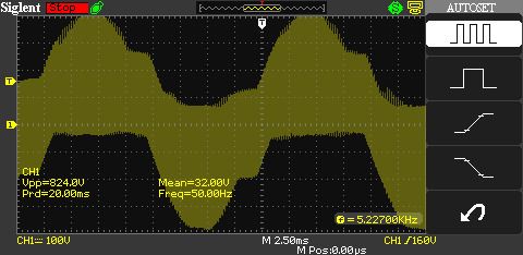
                                          I stuck an oscilloscope on my lathe's built-in VFD (can't find the blurb, think it's an 'inexpensive' Delta) and the output looks like this:

                                          p3wv.jpg

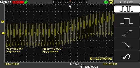
                                          It's an approximation of a 50Hz sine wave built of 5kHz pulses varied in amplitude. It's only 50Hz on average. Notice that the peak to peak voltage is 840V. Zooming in from 2.5mS to 250µS you can see the sharp internals better:

                                          p1wv.jpg

                                          So my particular VFD is pretty grubby. At 50Hz the waveform is full of spikes and harmonics extending from the 5kHz base to VHF. When the motor windings are correctly connected, the winding inductances smooth the spikes and the motor 'sees' 50Hz. What happens when the motor windings aren't connected properly is up for grabs. The spiky waveform is liable to resonate and create very high voltages. It's not hard to imagine a situation where a mis-connected motor winding accidentally behaves like a car ignition coil. There the contact breaker pulses all the energy stored in a condenser into the coil, causing it to poke out 10kV or so at the top. Even more volts when a spark lead is disconnected. (Ouch. You can guess how I know…)

                                          I'm sure that not all VFDs are as spiky as mine. I guess that many of the cheaper single motor units are as bad because the spikiness doesn't matter much provided they're wired up correctly. It's possible to clean up the output of a VFD and I reckon units designed to drive several motors do just that.

                                          Dave

                                          #325009
                                          Neil Wyatt
                                          Moderator
                                            @neilwyatt

                                            I backpedal on my earlier comments.

                                            My IMO Cub inverter does allow switching between inverter outputs and the motor. In fact it says the following about uising a magnetic contactor for switching:

                                            An MC can be used at both the power input and output sides of the inverter. At
                                            each side, the MC works as described below. When inserted in the output
                                            circuit of the inverter, an MC can also switch the motor drive power source
                                            between the inverter output and commercial power lines.
                                            ■ At the power source side
                                            Insert an MC in the power source side of the inverter in order to:
                                            1) Forcibly cut off the inverter from the power source (generally,
                                            commercial/factory power lines) with the protection function built into the
                                            inverter, or with the terminal signal line.
                                            2) Stop the inverter operation in an emergency when the inverter cannot
                                            interpret the stop command due to internal/external circuit failures.
                                            3) Cut off the inverter from the power source when the MCCB inserted in the
                                            power source side cannot cut it off for maintenance or inspection purpose.
                                            For the purpose only, it is recommended that you use an MC capable of
                                            turning the MC on/off manually.
                                            Note: When your system requires the motor(s) driven by the inverter to be
                                            started/stopped with the MC, the frequency of the starting/stopping operation
                                            should be once or less per hour. The more frequent the operation, the shorter
                                            operation life of the MC and capacitor/s used in the DC link circuit due to
                                            thermal fatigue caused by the frequent charging of the DC Link. If this is not
                                            necessary, start/stop the motor with the terminal commands (FWD), (REV)
                                            and/or (HLD), or with the keypad.
                                            ■ At the output side
                                            Prevent externally turned-around current from being applied to the inverter
                                            power output terminals (U, V, and W) unexpectedly. An MC should be used, for
                                            example, if a circuit that switches the motor driving source between the inverter
                                            output and commercial/factory power lines is connected to the inverter.
                                            Note: As application of high voltage external current to the inverter's
                                            secondary (output) circuits may break the IGBTs, MCs should be used in the
                                            power control system circuits to switch the motor drive power source to the
                                            commercial/factory power lines after the motor has come to a complete stop.
                                            Also ensure that voltage is never mistakenly applied to the inverter output
                                            terminals due to unexpected timer operation, or similar.
                                            ■ Driving the motor using commercial power lines
                                            MCs can also be used to switch the power source of the motor driven by the
                                            inverter to a commercial power source.

                                            #325016
                                            martin perman 1
                                            Participant
                                              @martinperman1

                                              Neil has just reminded me about how the company I worked for used their inverters, one piece of equipment had two three phase semi submerged pumps one running and one on standby i.e. after 24 hrs the running pump is stopped and the stopped pump is started up which then runs for 24 hrs when the process happens again, both pumps have contactors between them and the inverter and when the pumps are stopped the inverter is shut down to change over and the inverter is switched back on to ramp the pump back up to running speed.

                                              Martin P

                                              #325047
                                              Jon
                                              Participant
                                                @jon

                                                I will back Andrews emailer, i have been running an M300 for 8 years with original isolator, all contactors exactly as it was intended to be used ie with 3ph power.
                                                Done nothing to mine except plug the inverter in to machine exactly as if it were 3ph cabling in any industrial environment.

                                                To power inverter i just flick the 32A mcb c type switch and press Run thats it. Upon hitting Run hear all the contactors latch in. Now if put a 3 second delay ie slow start all it does is make the contactors chatter until voltage is reached.
                                                All i do then is hit the spindle start, job done and have all the original needed controls ie foot brake, coolant, spindle forward with reverse and all switches. Using any other way highly dangerous.

                                                As it happens just had a much smaller Mitsubishi D720-100 arrive this morning which will require a rewire and figuring out of the spindle start and foot brake or it wont get used.

                                                #325048
                                                Anonymous

                                                  There seems to be some confusion about what the output of a VFD looks like. Here is a sketch of a typical VFD output stage, essentiallly a 3-phase bridge:

                                                  vfd_output_stage.jpg

                                                  The 0V line is the same as the mains neutral and the DC_BUS is the rectified mains, around 320V for a single phase input. A motor is connected the the three terminals U, V and W.

                                                  Each pair of IGBTs can be in one of four states:

                                                  Both IGBTs off – the output will float and do it's own thing

                                                  Upper IGBT on, lower IGBT off – The output will be DC_BUS, minus the Vce(sat) of the IGBT

                                                  Lower IGBT on, upper IGBT off – The output will be 0V, plus the Vce(sat) of the IGBT

                                                  Both IGBTs on – exciting stuff, as the DC_BUS will effectively be shorted. Been there, done that as a result of a software boo-boo, short circuit current was on the order of 3000A. embarrassed

                                                  Let's assume the the IGBTs are fed with 1:1 mark:space square waves, so the upper IGBT is on for t seconds while the lower IGBT is off, then vice versa. The output will be a 1:1 square wave. If this is filtered it will be a DC voltage at half the DC_BUS voltage, ie, mid-rail. This is essentially the "neutral" point of the 3-phase output. If all three arms are driven in this fashion then any motor connected will just sit there, as the same voltage will appear on each terminal of the motor, at zero frequency, and no current will flow.

                                                  Now suppose we ensure that the upper IGBT is on for longer than the lower IGBT; filtering will result in a voltage above DC_BUS/2. Similarly if the lower IGBT is on for longer than the upper IGBT the filtered voltage will be lower than DC_BUS/2.

                                                  If we're clever with the upper and lower timings we can get an output that, when filtered, looks like a sine wave. However, the output of the VFD (on V, U, W) is a PWM signal swinging from 0V to DC_BUS.. It is not a sine wave or anything like, as there is no filter on the output. Since the IGBTs are either full on or full off the dissipation in them is relatively low, compared to them being driven linearly to produce a sine wave output – essentially an audio amplifier.

                                                  So how does that explain the SoD waveform? The 0V line is not usually brought out, so I think SoD measured phase to phase. This will give a sinusiodal like waveform, albeit with the switching waveform imposed on it. The spikes and noise are a combination of two effects. One, there will be parasitic L and C which will give spikes during switching due to high di/dt and dv/dt. Second, unless one is using a high quality probe with proper "earthing", the probe itself will generate "spikes" and "noise". The bog standard ground lead you see on 99.9% of scope probes doesn't cut the mustard for high speed measurements. It has too much inductance.

                                                  Right, still got a long list of things to do this evening. The first of which is check on the medlars simmering on the hob. The plan is to make medlar jelly, but at the moment the liquid is looking like brown goo, not translucent red. sad

                                                  Andrew

                                                  #325049
                                                  Ian Parkin
                                                  Participant
                                                    @ianparkin39383

                                                    Jon

                                                    Is your M300 just a standard machine ..no mods at all and is the inverter a 240v in and therefore 240v 3 phase out?

                                                    So you are running a 415v 3 ph machine on 240v 3ph ?

                                                    #325057
                                                    SillyOldDuffer
                                                    Moderator
                                                      @sillyoldduffer
                                                      Posted by Andrew Johnston on 02/11/2017 20:35:23:

                                                      There seems to be some confusion about what the output of a VFD looks like. …

                                                      However, the output of the VFD (on V, U, W) is a PWM signal swinging from 0V to DC_BUS.. It is not a sine wave or anything like, as there is no filter on the output. Since the IGBTs are either full on or full off the dissipation in them is relatively low, compared to them being driven linearly to produce a sine wave output – essentially an audio amplifier.

                                                      So how does that explain the SoD waveform? The 0V line is not usually brought out, so I think SoD measured phase to phase. This will give a sinusiodal like waveform, albeit with the switching waveform imposed on it. The spikes and noise are a combination of two effects. One, there will be parasitic L and C which will give spikes during switching due to high di/dt and dv/dt. Second, unless one is using a high quality probe with proper "earthing", the probe itself will generate "spikes" and "noise". The bog standard ground lead you see on 99.9% of scope probes doesn't cut the mustard for high speed measurements. It has too much inductance.

                                                      Andrew

                                                      Oooo! Andrew's post has given me much to think about. Did I measure phase to phase or not? I can't remember and, although I took notes, they're not in my usual book. So it's possible I didn't measure what I thought I was measuring; the point about parasitic LC rings true. It sort of aligns with what I was saying about the possibility of a mis-connected motor winding producing high voltages though.

                                                      Never mind, it's all educational. Back to the drawing board!

                                                      Cheers,

                                                      Dave

                                                      PS Mentioning Medlar Jelly flashed back me back 50 years to Sunday dinner. Mum used to make it. One year it turned out horrible and she gave up. Pity.

                                                    Viewing 25 posts - 26 through 50 (of 52 total)
                                                    • Please log in to reply to this topic. Registering is free and easy using the links on the menu at the top of this page.

                                                    Advert

                                                    Latest Replies

                                                    Home Forums General Questions Topics

                                                    Viewing 25 topics - 1 through 25 (of 25 total)
                                                    Viewing 25 topics - 1 through 25 (of 25 total)

                                                    View full reply list.

                                                    Advert

                                                    Newsletter Sign-up