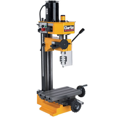
‘Squaring’ my mill.

Advert

‘Squaring’ my mill.

Home Forums Beginners questions ‘Squaring’ my mill.

Viewing 16 posts - 1 through 16 (of 16 total)
  • Author
    Posts
  • #241392
    Iain Downs
    Participant
      @iaindowns78295

      I'm not sure if this is the right term. however, here goes.

      If I put a dial indicator in my mill spindle, and traverse the table from front to back, i see a drop of about 0.12 mm. If I traverse it left to right then it's pretty much spot on.

      I'm open to being wrong on this, but I don't think that this is about head tramming, as the head isn't moving. Instead I theorise that the table is effectively at an angle with respect to the base.

      That is, that the back of the table is just a tad higher than the front.

      I expect I can sort this by shimming up my work, and am experimenting with this to see if I can get a (nearly) perfectly flat surface.

      I would expect that the proper fix is most likely to be to reduce the back X jib (the surface on which the table sits, if I have the name wrong). I guess this would need to go down by some 0.08 mm (I've not done the maths).

      How would I do this? Ideally, an approach that suits my limited equipment (clearly, I can't use the mill…) and even more limited skills.

      Thanks

      Iain

      Advert
      #8149
      Iain Downs
      Participant
        @iaindowns78295
        #241397
        Clive Foster
        Participant
          @clivefoster55965

          What make and type of mill do you have? Most of the common bench top machines have the upright column, whether round or square, bolted to the base. Square ones directly and round ones via a socket. Pretty simple with such machines to slip shims underneath at the front to bring it back to perpendicular to the table. Nice thing about working with shims is you know the thickness so its relatively easy to figure out exactly what ought to happen after inserting the shim and compare what you expected with the results you actually measure. If what you get isn't what you expect then nothing has been damaged or permanently altered so you can try something else. Trimming alignments can be very confusing until you get a proper concept of whats going on. If you have a good CAD program an hour or two playing around with drawings can be a great help.

          On an import Model Engineer market machine its probably a good idea to actually separate the column and base to ensure that the mating faces are true and clean with no itsy bitty contamination underneath. Takes very little to upset things by 0.12 mm. Being made down to a price you can afford production line fitting and fettling is limited with great reliance placed on the parts being made to adequate accuracy in the first place.

          If its an older, ex industrial type, machine the problem could well be wear as such machines were normally fitted to an good standard of accuracy when made. Sometiems clever shimming can sort the problems but many machines were made in a manner that preculdes this as in having nowhere to put the shims. Re working to eliminate wear and remove the error is a job for experienced people. Learning how to scrape and align machines is quite practical but you do need a mentor and a lot of time to acquire the skills.

          Clive.

          Edited By Clive Foster on 04/06/2016 17:47:08

          #241405
          Neil Wyatt
          Moderator
            @neilwyatt

            It is a tramming issue, but front to back, rather than side to side, solved by shimming or scraping.

            Clive: this is the type of machine Iain has:

            #241409
            Iain Downs
            Participant
              @iaindowns78295

              But not by shimming the column, I don't think.

              When I examine the block on a surface table as cut below I see a series of steps. In this case they jump up by about 0.01 mm each pass with the one nearest being ~ .06mm higher than the furthest. The ridges can be felt.

              Adding .05mm shim under the front end and taking the cuts again results in the front and back being the same height (+/- 0.01mm) and although there are still markings, they are much less pronounced.

              quarter step 2mm ps.jpg

              If this was the column tilting forward or back, I would expect to see the height consistent from the front to the back, but with each strip ever so slightly angled..

              So I think the table is tilted

              Iain

              #241411
              duncan webster 1
              Participant
                @duncanwebster1

                I had a similar prioblem with a Naerok many years ago. Put shims under the front (I think) of the column to tip it back. You won't need much, start with 0.002".

                #241419
                Martin W
                Participant
                  @martinw

                  If it is as Iain says that the gauge is held in the chuck and the only thing that is moved is the table then this surely is not a tramming problem but a fault with the alignment of the table in the Y traverse i.e. the surface of the table is not truly parallel with the dovetails in the Y plane of movement. The only way to improve this is to skim or scrape the table surface or scrape the guideways. No amount of packing the column will rectify the problem.

                  Martin W

                  #241420
                  Martin W
                  Participant
                    @martinw

                    Duplicate post

                    Edited By Martin W on 04/06/2016 19:54:10

                    #241424
                    RonMc
                    Participant
                      @ronmc

                      Martin is correct, if you tilt the column you will only tilt the cutting face of the milling cutter, the table will still move on the same plane.

                      The problem is the table and the slides are not on parallel planes. I mill a lot of aluminium, it requires sharp cutters and a cutting fluid, I use WD40 its the only real use I've found for it.

                      Edited By RonMc on 04/06/2016 20:09:31

                      #241431
                      Iain Downs
                      Participant
                        @iaindowns78295

                        Thanks, martin and RonMc.

                        Which leads me to ask how I would go about scraping the ways. I have a 8×12 (ish) surface plate (barely used) and some scrapers ('cos I thought I ought to have them), but this strikes me as something of a challenge. The ways are long and narrow and with a bit sticking up (down in normal operation) in the middle. They would need to be scraped so that the remain parallel (and flat).

                        I get the basic idea of scraping, but this seems to be graduate level rather than Ordinary level!

                        Iain

                        #241433
                        RonMc
                        Participant
                          @ronmc

                          Iain, I looked at your photos of your mill in your album, you aren't using a drill chuck when your milling are you, that will cause problems as they aren't designed to deal with the side thrust experienced in milling, they are designed to stand end thrust..

                          Best Regards Ron Mc

                          #241436
                          duncan webster 1
                          Participant
                            @duncanwebster1

                            Thought about it again, Martin is right, shimming won't cure what you described.

                            #241447
                            Martin W
                            Participant
                              @martinw

                              Edit; deleted as was not correct

                              Edited By Martin W on 04/06/2016 21:38:21

                              Bum It was OK – Start Again.


                              Something that might be worth trying and might make any correction easier could be :-

                              Slacken the gib screws on the X axis, I realise that might seem odd, lift the table and put a 0.1mm shim or feeler gauge between the horizontal surface above the gibs and the table horizontal bearing surface , full length of bearing surface if possible. Snug up the gib screws and re do the Y axis measurement. With luck this should have reduced or corrected the error, by trying various shims it should be possible to establish the thickness required to correct the error. If the rear X axis horizontal slide is reduced by this amount then I think this should resolve the problem. Having mentioned scraping I have to admit that I have never tried it blush others more qualified than me have often advocated it use!! A temporary fix would be to secure a shim between the front bearing surface of the X axis.

                              Martin W

                              Edited By Martin W on 04/06/2016 22:13:18

                              #241455
                              Neil Wyatt
                              Moderator
                                @neilwyatt

                                Skimming the table with a fly cutter is simpler and more likely to result in success.

                                It has to be the moving dovetail that is scraped if considering that approach.

                                The other tread suggests the gibs are loose, so perhaps the machine needs to be re-tested with them better adjusted first.

                                Neil

                                #241456
                                Martin W
                                Participant
                                  @martinw

                                  Made a mistake in my last post. For Front read Rear and for Rear read Front. Not only that but the font went awry as well.

                                  Martin

                                  #241458
                                  Frances IoM
                                  Participant
                                    @francesiom58905

                                    have you checked that the X table (that which moves L-R) is fully seated on the lower table and not riding on the top of the gib strips?

                                    the crop marks may well be due to backlash in the head/quill – there is a locking screw near the quill handle tho not the most convenient to adjust (there is somewhere on the web a mod by Meek – removed from this website – that showed a suitable and more accessible quill lock)

                                  Viewing 16 posts - 1 through 16 (of 16 total)
                                  • Please log in to reply to this topic. Registering is free and easy using the links on the menu at the top of this page.

                                  Advert

                                  Latest Replies

                                  Home Forums Beginners questions Topics

                                  Viewing 25 topics - 1 through 25 (of 25 total)
                                  Viewing 25 topics - 1 through 25 (of 25 total)

                                  View full reply list.

                                  Advert

                                  Newsletter Sign-up