Brooks Delta Configuration/Inverter Information

Advert

Brooks Delta Configuration/Inverter Information

Home Forums Beginners questions Brooks Delta Configuration/Inverter Information

Viewing 9 posts - 1 through 9 (of 9 total)
  • Author
    Posts
  • #75990
    Morgan Sweet
    Participant
      @morgansweet
      After helpful advise to my question on diference between a Myford Super 7 and 7B, I have decided to do down the path of a digital phase inverter with VSC, but am a complete novice regarding these electronice devises.
       
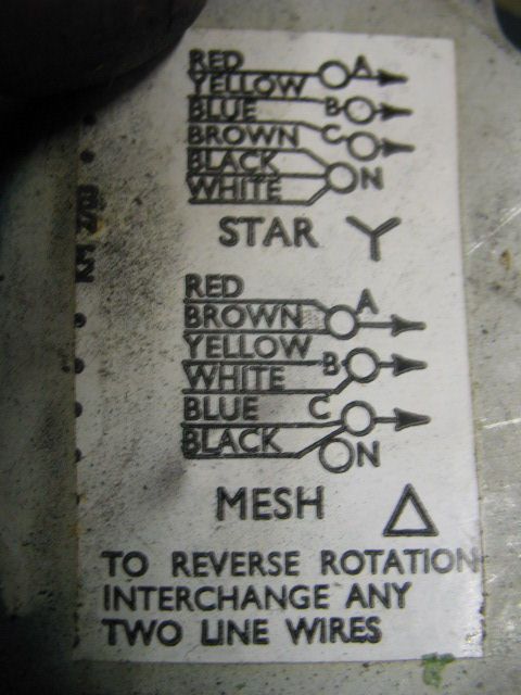
      The 3 phase motor is a 370W Brook Crompton Parkinson and has 4 terminals,
      A (RED), B (YELLOW), C (BLUE) and N (BROWN, BLACK & WHITE). The diagram on the cover plate has disintegrated and I’m assuming teminals ABC are phase 123 respectively and N has the 3 wires bunched and is in star configuration. There are no straps etc, so I hope to take the N wires off and bunch with the appropriate ABC terminal wires to give me a Delta (240v) configuration. Does anyone know what wire goes with what?
       
      Further if I buy a 1 phase to 3 phase inverter can I use the existing Dewhurst reversing switch etc, or do I have to obtain a control box? Also can I make a control box, is there a wiring diagram, is it just switches with a potentiometer of what value etc. Are these digital inverters compatible with CNC electronic circuitory?
       
      Thanks for any information
      Advert
      #5693
      Morgan Sweet
      Participant
        @morgansweet
        #75995
        Weldsol
        Participant
          @weldsol
          Re your motor wiring you could try MM Engineering as they are Brook, motor specialists 01274 288777
           
          Re the reverse switching you will only be switching the control voltage of the inverter (12 or 24 v) and is normally a two wire connection (well it is on my two inverters) I have mine working through the controls on the machines but they are wired to suit . for the speed control you need to check with the inverter spec to see what value pot is required.
           
          Paul
          #76003
          _Paul_
          Participant
            @_paul_
            This is the motor wiring
            I wouldnt use the drum switch it may harm you inverter, you will have to construct or buy a control pod to suit you particular inverter lots on Fleabay, look for Drives Direct Dave is very helpful (usual disclaimer).
            I made my own pod cost about a tenner took me a while to work out the wiring on my inverter and the component value required:
             
             
            Regards
             
            Paul
             
            #76006
            Morgan Sweet
            Participant
              @morgansweet
              Thanks Paul for the information, is the POT a 10K linear as opposed to Logarithmic?
               
              Thanks
               
              Morgan
              #76020
              _Paul_
              Participant
                @_paul_
                Linear from here Farnells
                 
                Regards
                 
                Paul
                #76080
                Morgan Sweet
                Participant
                  @morgansweet
                  Thanks again Paul.
                   
                  Morgan
                  #76095
                  Steve Garnett
                  Participant
                    @stevegarnett62550
                    Posted by Morgan Sweet on 08/10/2011 11:55:43:

                     
                    Further if I buy a 1 phase to 3 phase inverter can I use the existing Dewhurst reversing switch etc, or do I have to obtain a control box?

                     
                    You absolutely can’t use the Dewhurst switch as it stands! Well, not unless you want to increase the odds of blowing up the inverter by a staggering amount, anyway. But I think that the Dewhurst switch can be rearranged quite simply to work as the 3-way switch shown (which, erm, isn’t a Single Pole Single Throw, because it has a centre-off position), and use it to control the inverter instead. Doing this gives you controlled acceleration/deceleration as well, so it’s definitely the way to go if you can figure out the connections to it.
                     
                    I have one of the same inverters that _Paul_ has, and it’s really easy to control, as he has demonstrated. There is at least one additional function that it can easily be made to do as well – jog the motor in small increments. Sometimes this can be useful… but they are good inverters, as long as you keep them covered. Unfortunately the microprocessor control section is right at the top, and vulnerable to anything (like oil mist) falling in there. Yes, I found this out the hard way! Fortunately, a quarter of an hour in an ultrasonic cleaner, a rinse down with de-ionised water and an hour in a temperature-controlled oven cured it completely.

                    Edited By Steve Garnett on 09/10/2011 22:49:55

                    #76103
                    john fletcher 1
                    Participant
                      @johnfletcher1
                      I have 3 pre ownd inverters all different makes and the control circuits are all low voltage so it is easy to make your own remote control box as the earlier diagram shows. One needs a 10K pot for speed control and the other two 5K. A useful thing about inverters you can flick the forward and reversing when screw cutting up to shoulder, the motor slows down and ramps up in the opposite direction.Oh, that’s another useful attribute of inverter control ramping up no sudden on.I have noticed that some internal controls are not changable on some ebay advertised inverters. When I bought two of mine from an auto jumble sale I got the manufactures phone number from their web site and gave them a call, they were extremely helpful.Regarding ventilation, I mounted a piece of sheet alumnium with a slightly bent front about 50mm obove my inverters this deflexts any swarf or dust. All 3 were intended to be cabinet/panel mounted,fortunately I had a selection of boxes in which to mount them in (one each) I cut a hole in top and bottom fixed some fine mesh over the holes, then as I said fixed the dust/swarf deflector plate, that was 3or 4 years ago.i hope that gives you some ideas,Ted
                    Viewing 9 posts - 1 through 9 (of 9 total)
                    • Please log in to reply to this topic. Registering is free and easy using the links on the menu at the top of this page.

                    Advert

                    Latest Replies

                    Home Forums Beginners questions Topics

                    Viewing 25 topics - 1 through 25 (of 25 total)
                    Viewing 25 topics - 1 through 25 (of 25 total)

                    View full reply list.

                    Advert

                    Newsletter Sign-up