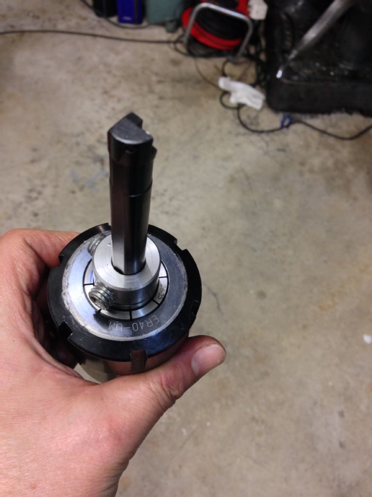
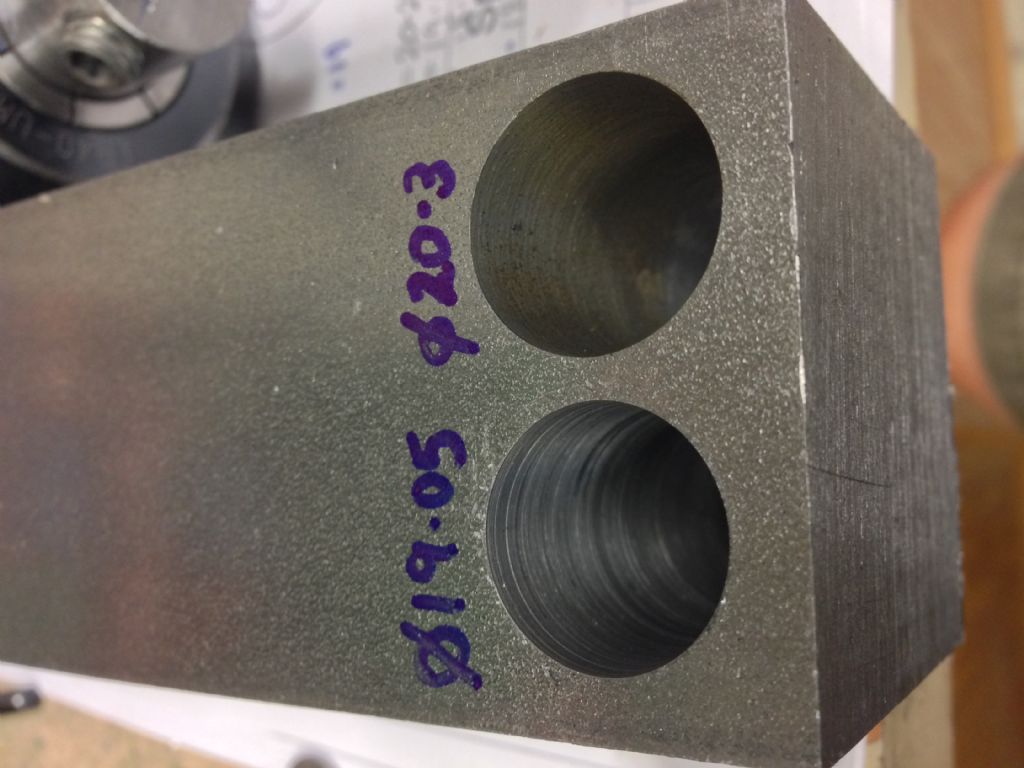
Here's a simple boring head I've just made up for machining some 19mm bores into a steel D1-3 spindle nose body. If I manage to complete the machining process without any outrageous errors, I will end up with a base that accepts my various lathe chucks and faceplate and will bolt down to the milling machine table or rotary table.
You'll probably look at this and think it's not a boring head at all, just a boring bar holder. However, due to the offset of the cutting edge relative to the axis of the bar itself and due to the eccentric hole it fits in to, it is actually an adjustable boring bar head requiring minimal effort to make – my kind of tool!
I have 2 Glanze indeable boring bars that take the CCMT 6mm inserts that are also used in my lathe tooling. These are 12mm shank (6mm radius, then) and have a cutting edge that is 9mm from the central axis. Mounting this directly in a collet chuck will result in a hole of around 18mm diameter. However, as we know, it is possible to bore a smaller hole with these boring bars by bringing the tool off axis, eg in a common lathe useage. Glanze claim a minimum achievable bore diameter of 16mm but in fact you might arguably be able to get down nearer 15mm (6mm shank radius plus 9mm to the cutter edge), if you are not worried about maintaining much of a clearance to the tool in the bore.
Mounting the bar in an eccentric 12mm hole drilled into a piece of round bar would allow the head of the bar to be rotated relative to the offset angle and thus give an infinitely adjustable cutting edge offset between 2 extremes. With the above mentioned tool and an offset of 1.5mm, a nominal hole size range of 15 – 21mm should be possible, on the face of it. Obviously any error in how parallel and straight the bar and hole are will affect those numbers.
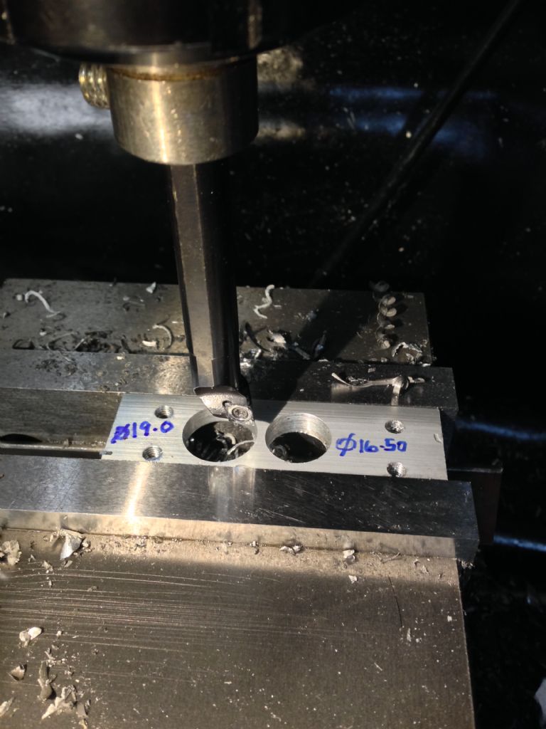
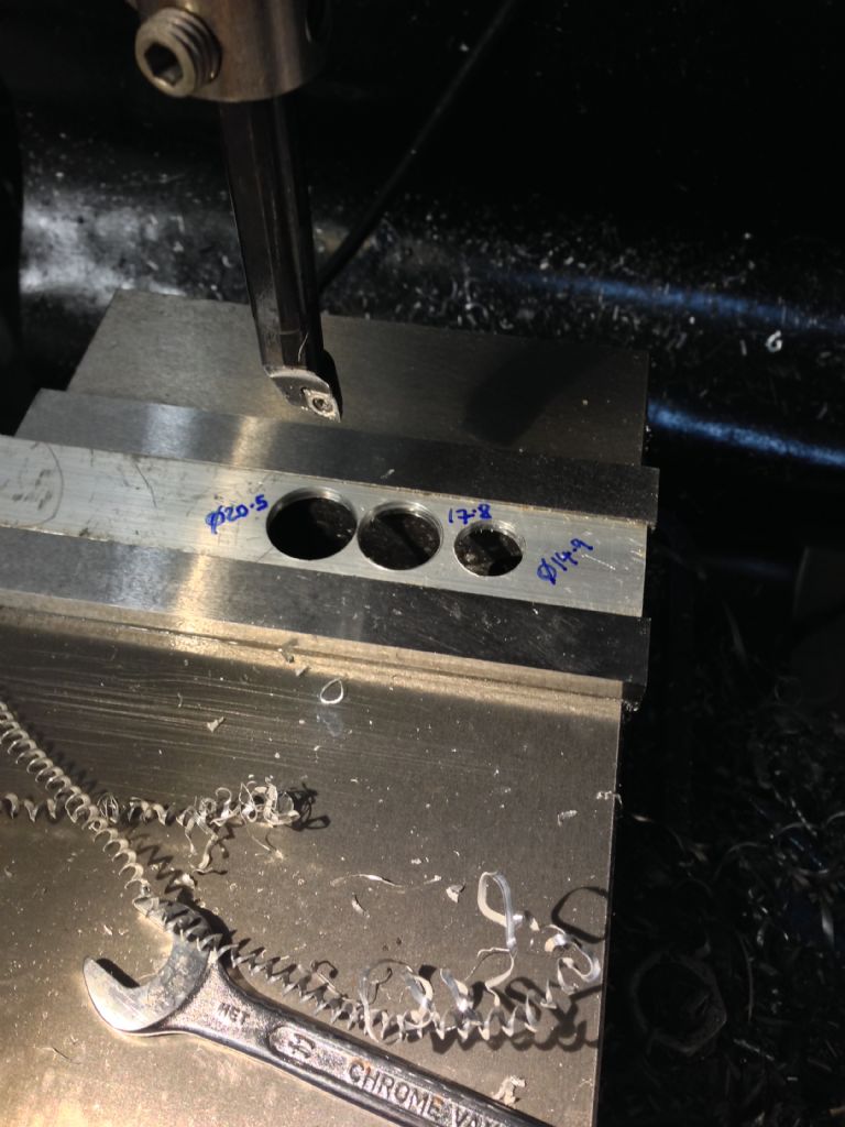
I took a 3" length of 1" ground stainless bar I took from the ark(!) and drilled a 12mm hole through at a 1.5mm offset, using a slot drill for the first 35mm of the final pass, then drilled and tapped 2 x M10 threads radially into the end for retaining grub screws. With this in my ER40 collet chuck, I did some trial holes into some loominum, then some steel – a 14mm drill followed by passes at the min, mid and max positions. These measured at 14.9, 17.8 and 20.5mm. Not bad.
With this arrangement, when the tool is at the max or min position, the insert is presented to the work at the default recommended angle (several degrees below horizontal). However, somewhere not far from the midpoint, the cutting edge reaches a maximum angle of around 6 degrees further below the horizontal. However, the effects at the cutting edge should be second order, as the tool will be mostly cutting axially, not radially, assuming a reasonable depth of cut relative to the tip radius.
My aim with this was to maximise the rigidity of the setup without simply blowing loads of dosh on "proper" tools and to me it looks as if this is about as simple and robust as you can get. The proof of the pudding will be when I attempt the full 30mm depth of the 19mm bore into steel for real (3 times!). I'm sure this isn't a novel technique but it's not something I've personally encountered before.
I also made up a second version that had a smaller, 1mm offset that gave an adjustment range of 16.5 – 19mm, much as you might expect. This would allow finer control of the depth of cut due to adjustments of the angle. For my 19mm holes, that might be the better choice, starting with a 16.5mm drill.
Merry


Muzzer.


