Not only did it play an essential role in an elaborate drive system, its unusual performance made it an intriguing little gubbins in its own right.
In today’s jargon the jeclanide handwheel is ‘transparent’ when operated from one end – and rigidly ‘solid’ when torque is applied to the other.
The prototype was one of a number of home-brewed gadgets scattered round your scribe’s office. (The forerunners of today’s Executive Toys?).
Enjoy more Model Engineer Magazine reading.
Click here to subscribe & save.
Clamped to a convenient support, it roused the interest of many clients. By twiddling its handwheel, they could swing a weighty lever arm from the nine o’clock to the three o’clock position, never failing to be intrigued by the way the arm stubbornly refused to budge from any lop-sided position set by the handwheel.
Its silver steel shaft carried battle scars, ample evidence that over-enthusiastic types had used excessive force against the little man inside – but he always stood his ground.
Top secret!
Curiosity led most observers to request a view of its innards. Repeated dismantlings accompanied by a need to smooth away the shaft’s latest crop of wounds prompted a larger version in Perspex, its modus operandi thereby exposed to view. Glass clear and polished it never failed to gain attention and, like its smaller brothers, proved capable of resisting any tendency to rotate when unbalanced loads were applied to its silver steel shaft.
The original device played an essential role as part of a drive system built into a large training aid supplied to the M.O.D. To avoid violating the terms of the Official Secrets Act, let’s call it a display based on the pigeon and its homing instinct…
Incidentally, the display mechanism had to incorporate an ’inertia factor’, the attack and decay time being influenced by the distance between pigeon and loft. (It was essential for the display to include a symbolic time lag to indicate inertia effects in the full-size system. In real life, there’s time – and occasionally a need, for a prayer meeting after slamming on the brakes of a supertanker, for instance).
But first a word about differential gears, six of which – all interconnected – were incorporated in the display drive. Perhaps the most familiar application of a differential gear is that located in a car’s rear axle; the drive being applied via the prop—shaft and crown bevel gear to the planet gear spider and thence to the sun gears on the two half—shafts driving the road wheels. Viewed from above it follows a basic ‘T’ shape; the input applied via the leg, outputs taken from both ends of the cross bar.
Spot the differential!
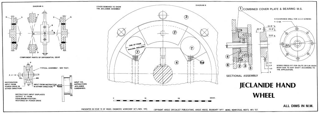
Diagram A identifies components of all six diff units incorporated in the display mechanism. A typical diff assembly is also shown. (Together with notes relative to the specific unit by which the instructor fed commands into the display, about which more below).
Instead of driving the spider by a crown wheel, the spider-boss (B) complete with two stub-shafts is fixed to a central shaft (A). Two bevel planet pinions (P) are free to rotate on the spider stub-shafts, held captive by circlips and washers.
A pair of bevel gears (S) – the sun wheels – are free to rotate on the central shaft (A), again held captive by circlips and washers. Both sun wheels have spur gears (G) attached, their PCDs selected according to the ratio required when meshed with their respective drives. (We obtained all our gears from S.H. Muffett Ltd, Tunbridge Wells, Kent- usual disclaimers – but for those interested in building an experimental diff, take a tour round second hand shops and select two identical bevel drive hand drills).
The display had to reproduce all aspects of the cause, effect and corrective measures used in restoring a disrupted state of equilibrium so, as may be expected, some of our diffs operated in the car-mode, others followed a slightly different operating mode whereby two inputs were applied to the ends of the ’T’ cross bar and the result taken from the leg.
With reference to the assembly in Diagram A, the instructor’s jeclanide handwheel rotated the manual input of a diff operating in the double input mode, i.e., turning the handwheel rotated the ’manual’ sun wheel (NIS) of the pair, the other sun wheel (PS) being coupled to the power driven mechanism. In the neutral or equilibrium state, the differential unit was at rest. (ie. the pigeon in its loft). By turning the handwheel, the instructor could move the pigeon to some remote spot, thereby disrupting the status quo.
At the differential, the high resistance to rotation of the motor driven mechanism ensured that sun wheel (PS) was too stiff to be turned by hand. Consequently the rotation applied by the instructor to his manual sun wheel (MS) caused the planet wheels to roll round the ’drive’ sun wheel (PS), thereby rotating the spider and its carrier shaft (A) away from the neutral equilibrium position.
From a slow start, the mechanism gradually responded to the non-neutral state, the power drive rotating its sun wheel in the correct direction to restore matters. It gradually decelerated as it approached neutrality, so preventing an overshoot as the spider and its shaft regained the original neutral position.
Needless to say, there was much more to the system, but it was vital that whenever power was applied, it caused the planet wheels to roll round an unyielding manual sun wheel, otherwise, instead of returning the spider shaft to its original equilibrium position, the power drive would merely spin the handwheel.
Consequently it was necessary to prevent the manual sun wheel from rotating when twisted from the diff end while at the same time leaving it completely free to turn either way when twisted from the instructor’s end.
Clutching of straws
A self-sustaining worm drive would have involved far too great a reduction and was ruled out as too slow. As we suspected, no manufacturer bred mongrels to meet our spec. Some sales staff tried to convince us that a pair of one-way clutches would do the trick, initially failing to grasp that what we required was no ordinary one-way clutch unit but one which presented a non-resisting drive when twisted either way at its input end and a rock-solid resistance to any twisting at the other.
Telephoned enquiries elicited a good natured: ‘and the best of British luck’. Written enquiries took longer to get a similar message in writing.
Once again we were on our own.
One German manufacturer sent a sample one-way clutch which provided an opportunity to study its innards; virtually a stub·tooth ratchet wheel with a spring loaded roller sitting in each tooth and surrounded by a brake drum. Turn the ratchet one way and the rollers wedged solid between teeth and drum, turn it the other way and it free-wheeled. lt took a while for the penny to drop, yet it stared us in the face. Stripped to its components, the outer drum, ratchet, rollers and springs lay in a tray. Toying around with the bits, the ratchet was replaced in the drum along with one roller and spring. Even one roller gave a remarkable non-return effect. When jammed, it took a little effort with a small screwdriver to dislodge the roller from its wedged position, but when relaxed, the only force required was that needed to compress the roller spring. Continued pressure from the screwdriver forced the roller to the back of the tooth, then moved the ratchet- in the direction previously prevented by the jammed roller — the very action we were seeking. The germ of an idea formed… A home brewed four-tooth ratchet was hastily filed to shape; two right hand teeth and two left hand teeth, paired on perpendicular axes.
As a try-out, two rollers were set in adjacent teeth, both forced forward into the wedge position by springs. Sure enough, the ratchet shaft jammed, refusing to budge in either direction.
Working like a charm
Pressed by a small screwdriver, first one roller and then the other was forced against its respective spring, whereupon the hybrid ratchet moved accordingly – just what had been hoped would happen. Fitted with all four rollers and driven by an inverted ‘U’ shaped driving yoke in place of the screwdriver, the rough little gubbins worked like a charm, moving freely when turned in either direction by the yoke, yet resisting all attempts to twist the ratchet shaft. A right little jeclanide.
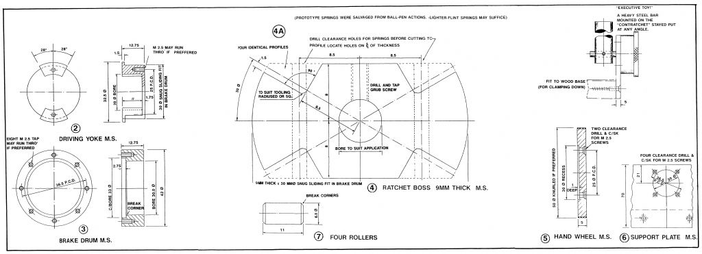
The eventual outcome is shown in Diagram B. The cover is removed to show the non-rotating brake drum (Item 3), two of the four rollers (Item 7 ), the ratchet boss (Item 4), the two roller springs (Item 4A) and the hand operated driving yoke (Item 2).
In its relaxed state, the two springs force the rollers into close contact with both the ratchet and brake drum, locking them together as one. Turning the yoke in either direction forces the appropriate pair of rollers out of the wedge mode and allows the ratchet to rotate accordingly, the other roller pair trailing in ‘free-wheel’ fashion.
The driving yoke (Item 2) and the ratchet boss (Item 4) were made in that order from a reasonable length of trued 35mm bar stock, turned to 30mm dia. to within a few mm of its end face, leaving stock to form the collar. The yoke was turned and bored then milled in the lathe to leave two lugs, each having a 56 degree included angle between faces, following which it was parted off to length.
The remaining piece of 30mm dia. stock was re-faced, centre drilled and then milled to form two flats, after which it was cross drilled to suit the springs. We salvaged springs from discarded ball pens but, in retrospect less bulky lighter-flint springs may have been a better choice.
Once the drillings were completed, the four ratchet teeth were milled. We fixed the chuck at 30 degrees above and 30 degrees below horizontal and used an end mill, cutting two teeth at two settings, then repeated the manoeuvres for the opposite pair.
The remaining items are straight forward machining tasks, responding as always to accuracy and attention to detail.
For the Executive Toys, a support plate (Item 6) was fixed to a wooden base, long enough to provide accessible areas for clamping down.
With regard to the original application, a fractional degree of lost motion was of no concern from the instructor’s point of view. However, as an experiment to satisfy our curiosity, one of the subsequent units had a solder layer added to each face of the yoke lugs in an effort to minimise lost motion. It proved highly effective and was noted for further reference.
lf experience with the prototype is any indicator, your jeclanide will create much curious interest. It may lead to a duplicate in Perspex, if only to avoid the need for frequent dismantlings.
Download sheet 1 of the plan as a PDF HERE
Download Sheet Two of the Plan as a PDF HERE
For those with A4 printers and a passion for cutting things aout and putting them back together with sticky tape, here is the plan as eight separate pages. Please use round-ended scissors and ask an adult to supervise you. We cannot take responsibility for missing digits:
Page 1
Page 2
Page 3
Page 4
Page 5
Page 6
Page 7
Page 8
As always, respect to Nick Farr for scanning the original. Kudos to me for having the patience to scan in and OCR W.B. Taylor’s witty article – just what were his mysterious ‘homing pigeons anyway? Torpedos? Nuclear missiles?
Enjoy this plan, but if you do decide to make one and decide you have wasted several months of hobby time on it, it’s your own fault.
Neil Wyatt


