This page includes the full entries for this years’ competition. You can cast your votes here: tinyurl.com/55c35b3s
Dave Sanderson – CNC mill
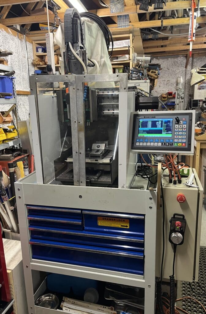
As my projects now include shapes which are not trivial to manufacture by manual means I decided I needed a small CNC mill. The majority of intended use is for small (under ~100mm XYZ) parts.
The design is a fixed gantry carrying X and Z, with a moving table in Y. This layout is intended to allow high accelerations with good rigidity in a small footprint as needed for a machine with high speed spindles and small cutters.
Enjoy more Model Engineer Magazine reading.
Click here to subscribe & save.
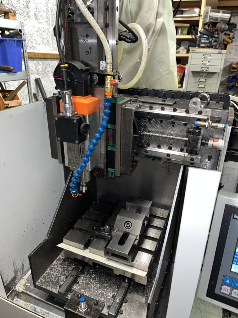
I already had a 24000rmp, ER16 spindle from a previous project and decided that travels of ~150mm in XY and Z was ‘about right’.
The base is a Cast Iron surface plate of the approximate correct size that I found on EBay. This was then hand scraped flat to give a good base reference surface to align the rest to and for the linear rail ways. The ball screws are 12mm x 4mm pitch.
The main structure was designed to be laser cut from plate steel of varying thicknesses. It is of a box design with tabbed construction for ease of assembly and a closed back to increase the rigidity.
It ties the 2 main columns of box section that carry the gantry rigidly to the surface plate base. The gantry itself is a large 12mm plate, which in turn is backed by a 50mm deep ribbed weldment which I surface ground flat.
This carries the X axis carriage, which is made from a pair of Hemmingway surface plate castings (cheaper and lighter than lumps of Cast Iron). These were machined, scraped and aligned to carry the Z Axis and X axis linear rail cars. I opted to have the rails themselves on the Z axis ‘quill’ as it seemed more rigid than the other way round as on Chinese CNCs. The ‘quill’ carries the spindle and lead screw and is HRS channel which is machined appropriately.
All the rails are aligned in the same manner – Linear rails are not necessarily straight and are designed to be pushed into an alignment feature on the machine. As I had only flat scraped surfaces, I did not have the required edge, so the rails are aligned using countersunk SHCS, which wedge a round bar into the rail side. By adjusting the opposing screws a powerful and controllable alignment can be created. One rail was first aligned straight (using a surface plate and indicators), then its part was aligned parallel. The C-C distance was controlled on the car mounts, such that all the ways are aligned and non-binding.
The Table is machined from a WDS Cast Iron CNC fixture plate. This came with T slots that match my main Mill and has pockets to carry the linear rail cars on the underside.
The control system is housed in a steel cabinet bolted to the stand. It has power supplies for the steppers and DDCS Expert controller and switch gear and filter for the VFD drive for the spindle.
You can cast your votes here: tinyurl.com/55c35b3s
Brett Meacle – Slip On Rear Spindle Steady
One job that comes up occasionally is a need to work on a long workpiece that needs support at both ends of the headstock. This is for a couple of reasons. One to stop it flailing about for safety, which is a most important consideration. Secondly, to support it concentrically to ensure greater machining accuracy of the workpiece. A rear spindle steady or spider, is used to hold the work concentric and supported.
In the past I had fitted a rear steady as part of the spindle bearing adjustment setup on far eastern 920 style lathes, using a threaded steady to lock the bearing adjustment nut when the bearing was adjusted correctly. The spindle steady being permanently attached for use at any time, with the sheet metal headstock cover modified to suit.
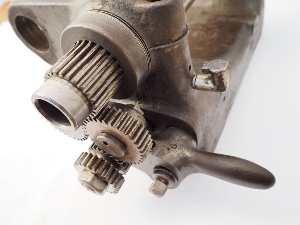
When it came to fitting this attachment to a couple of other machines, I found it was not possible as the bearing arrangements were different. Lathes like the South Bend 9” have a plain machined surface on the end of the spindle, Photo 1. The Myford super 7 has both a screwed section and a plain portion, allowing some choice, but a drawback with fitting a steady to either of these lathes permanently, is the fact the cast belt/change wheel guards do not lend themselves easily to modifications to accommodate a rear spindle steady fitted full time. Thoughts turned to an attachment method using the plain spindle portion to attach the steady only when required.
Inspiration for a clamping method came from Graham Meek’s “Projects for your Workshop” book, this was a clamping arrangement to tightly grip an adjustable stop rod allowing for smooth adjustment and no damage to the rod from repeated adjustments. Why not increase the size to grip the outside of the spindle, allowing a firm grip, no damage, and fast fitting/removal.
Photograph 2 shows the slip on version has two components, the main body and a clamp ring plus the screws. A socket set screw in the clamp ring applies pressure to the collet fingers of the main body, with close machining, the actual movement to lock the steady onto the spindle is minimal.
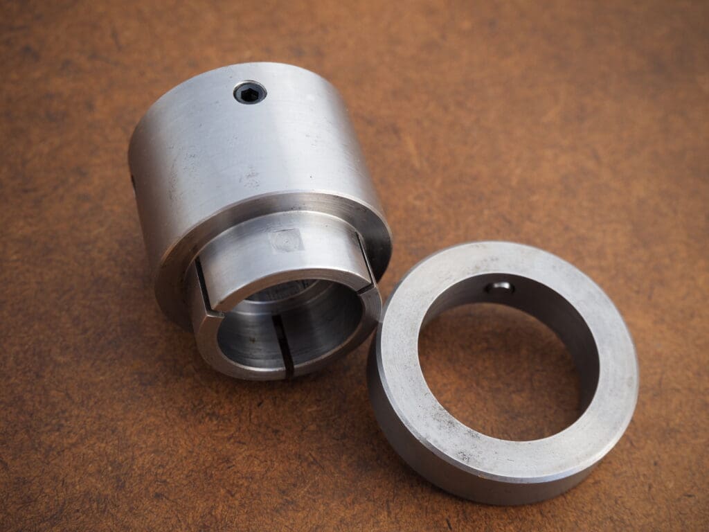
Machine the recess and collet finger section a close smooth fit to both the spindle and clamp ring.
The collet section was cut into 3 segments to ensure a good clamping action. A flat is also machined for the clamp screw to bear on, allowing the clamp rings removal without a raised burr causing problems. The threaded holes and the adjuster screws complete the job.
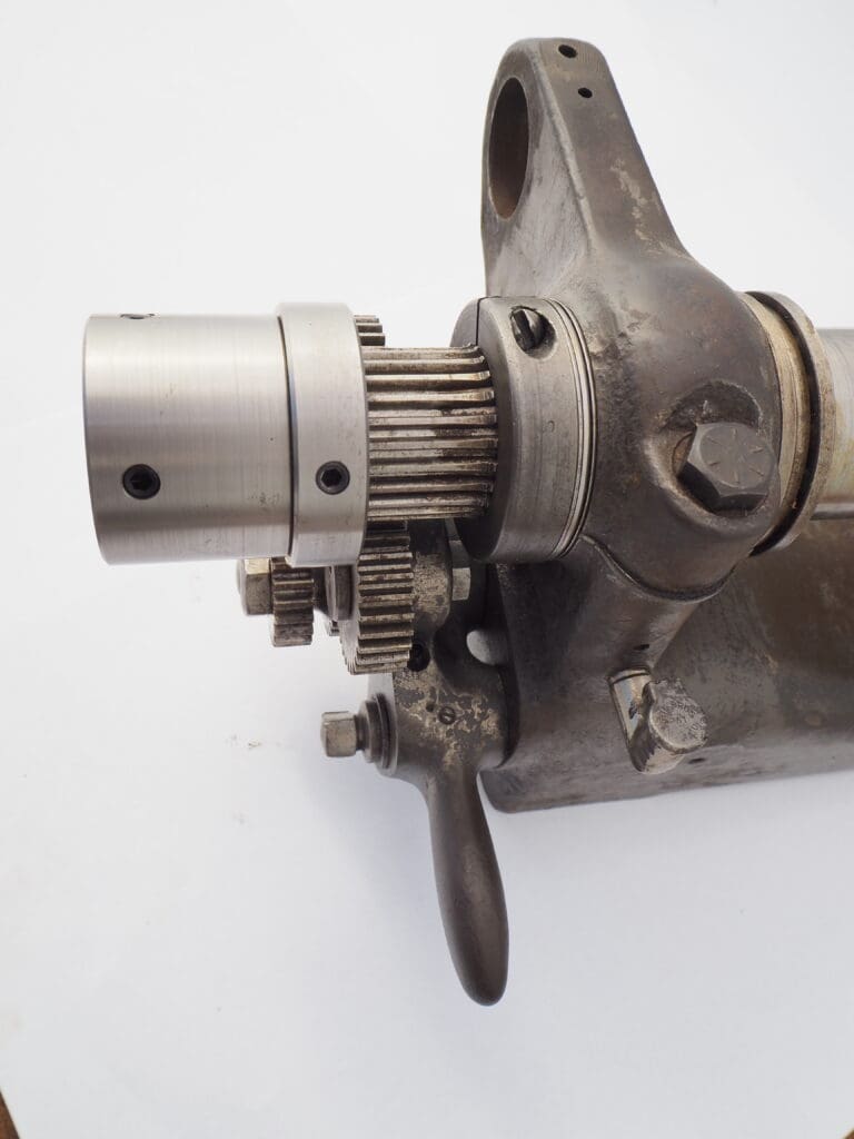
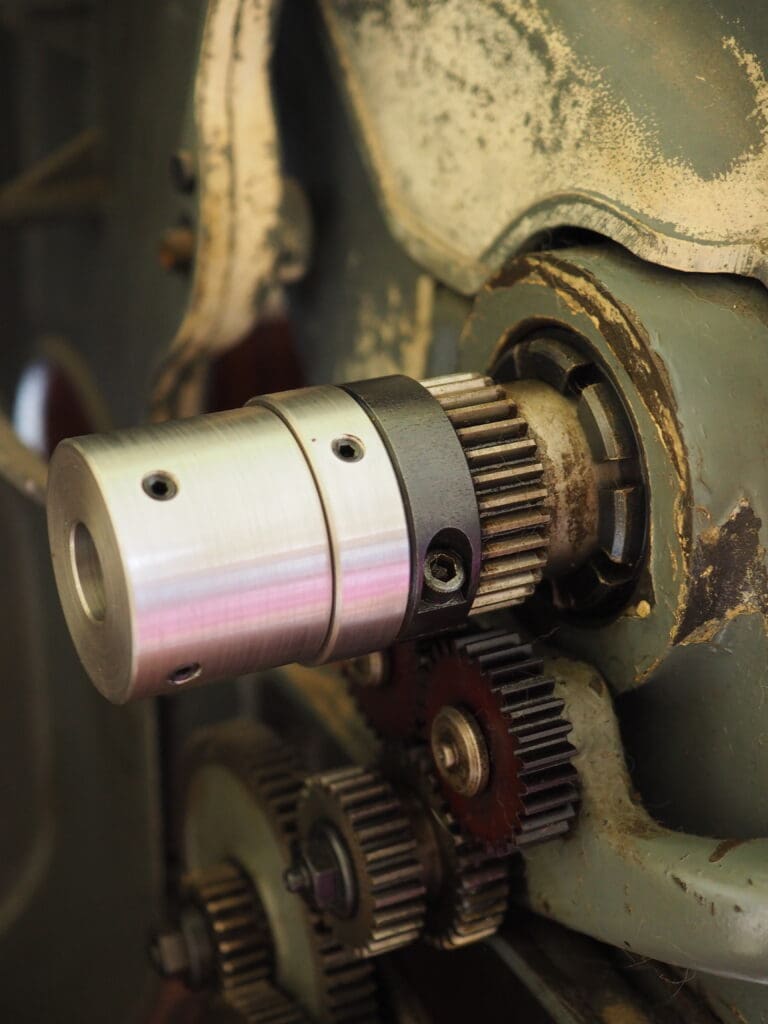
Photograph 3 shows the finished item installed on a South Bend 9“ lathe and a Myford Super 7, Photo 4.
Once completed you will have a useful accessory for your lathe, an item not used every day but is one of those handy to have accessories that may save the day when needed, alternatively it’s a quick job to make if that day arises.
You can cast your votes here: tinyurl.com/55c35b3s
David George – Taylor Hobson cutter grinder modification
I have a Taylor Hobson Pantograph cutter grinder which I modified with a table to grind turning tools etc. and decided to give it further options so I can regrind or make milling cutters made with high speed steel and tungsten carbide.
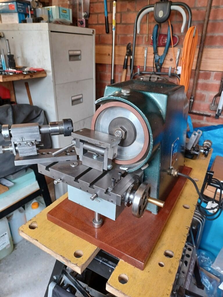
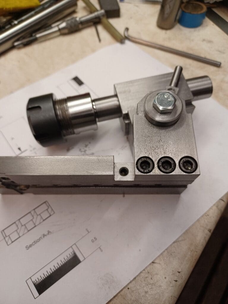
I started by finding a top slide from a lathe as a base for the slideway which I picked up at the Midlands Model engineering exhibition last year. The base was a solid piece of cast iron which I machined to fit the mounting holes on the grinder and a dovetail slideway to match the top slide. I designed the tool holder to take a ER25 standard collet set with a 20mm long shaft.
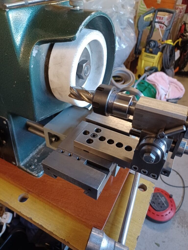
The collet block which has a locking clamp and dovetail slide with adjustable in and out feed screw is mounted on an angle plate which allows tip forward and back and rotation radially if necessary. The main top slide has a feed screw with dial which gives left to right movement with a handle on the right hand side. I have so far ground a drill point and a 20mm HSS milling cutter with great results. Also I have reinstated the table so it is still available to grind turning tools etc. as well. I had use a diamond wheel for Tungsten carbide cutters and white aluminum oxide wheels for HSS cutters and drills.
As I already had a diamond wheel I was going to use, that but as it had been used already by me for various tool grinding etc. it would need dressing for cutter grinding. I bought a diamond wheel dressing attachment which has been used with good effect and the wheel is sharp and true now.
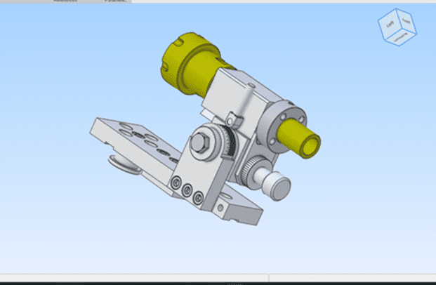
The collet block has a removable dowel which matches radially with a ring which has four equally spaced holes which allow cutters or drills to be set to depth and rotated to position to match the cutting edge position for every grind position. The angle plate can be clamped with a T nut square to the traverse or lengthways along the bed as well as a round location nut which allows for end angles on cutters or drill angles as well.
You can cast your votes here: tinyurl.com/55c35b3s
John Cuckson – A Precision, Workshop Hoist
Light industrial machines have many attractions but moving them or their attachments is not one of them. I now find the 40 kg work heads of the Myford MG12 cylindrical grinder increasingly heavy to lift and align with the tee bolts in the machine table.
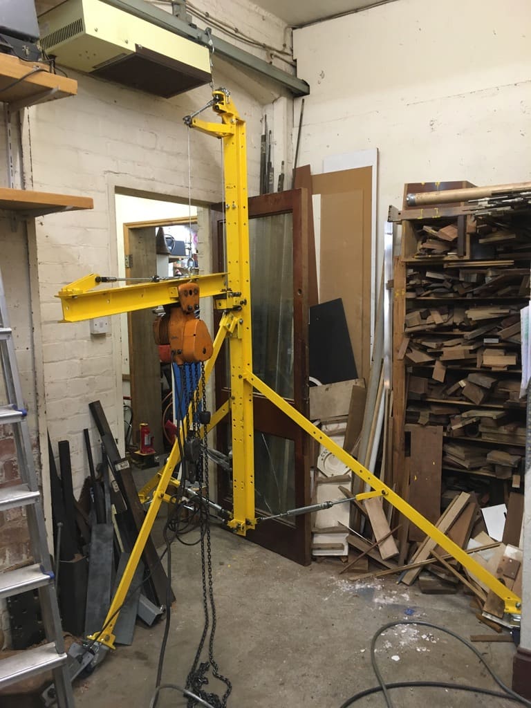
When a slewing jib electric hoist with a bunch of metalwork came to auction, I saw a solution. My machines are either back-to-back or against a wall, so required slew is limited. I cut the original jib (a 3 inch by 4 inch universal beam) in two to make a column and a shortened jib and cut the original 2 inch by 1/2 inch stay bars to form an adjustable Tee-shaped tripod on castors to suit the grinder and other machines. Because the tripod’s legs are parallel to the wall or the machines, the hoist takes up very little floor space. But checking static stability with the hook at different radii and slew angles and different tripod footprints is important. Reliable stops to limit the slew are essential because the tripod becomes seriously unstable if swung too far. It is also important to check the elastic stability of the tripod legs, as well as the strength of the tension stays that connect them to the column plus all other connections.
However, while solving the problem of lifting the work heads, the device itself is heavy (35 kg column, 20 kg jib, 25 kg electric hoist). So I designed it to be assembled using a hand operated cable puller working on a sheaved cable that enables sufficient vertical travel to lift the jib and electric hoist from near floor level to the top of the 2.3 metre column.
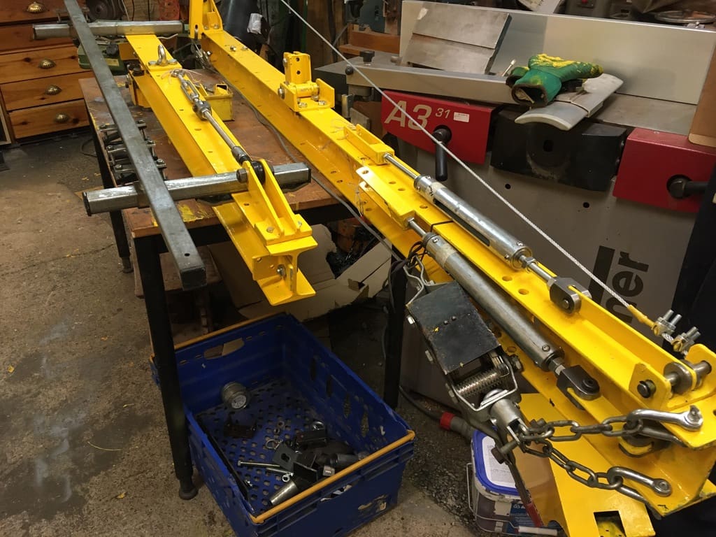
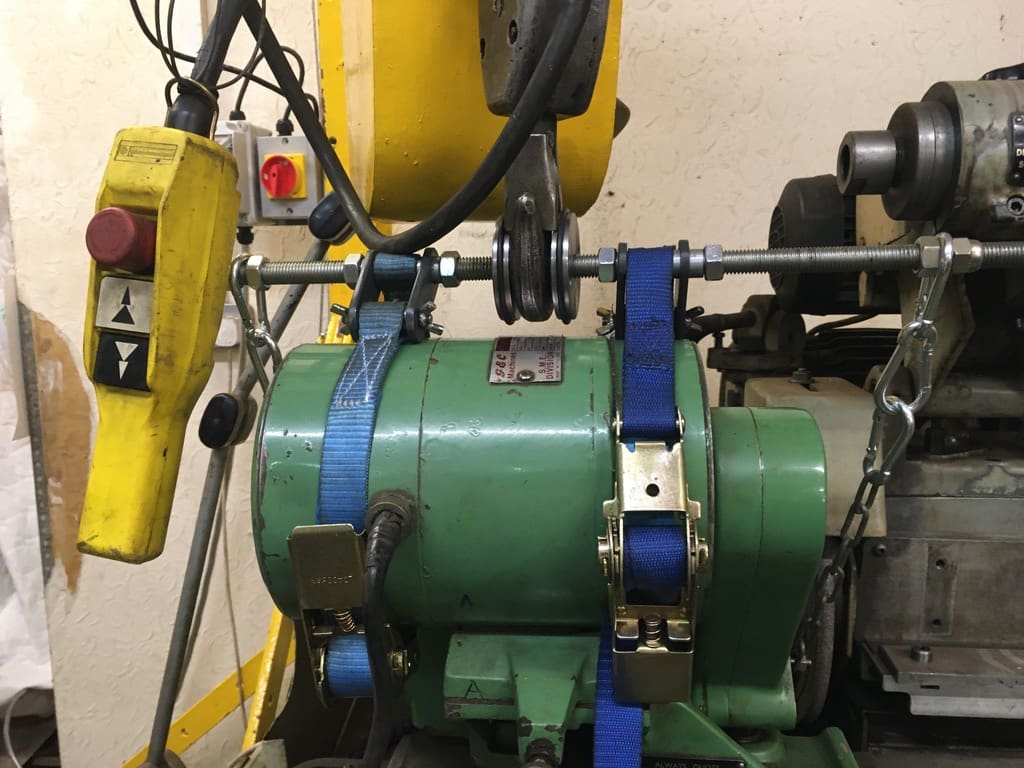
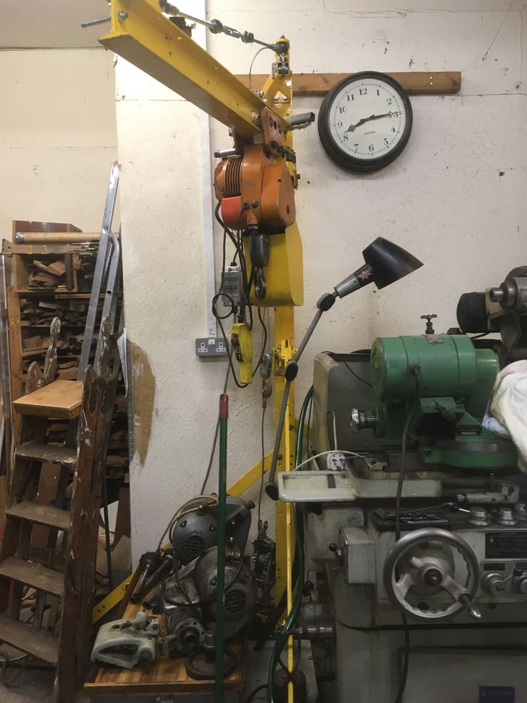
The first step in assembly is to fix the adjustable tension stays to the column. This has holes in the flanges and web to allow different spans for each tripod leg for different machines (see photo 1). The column is lifted into a vertical position and stabilised. The tripod legs are then pinned to the column; the tension stays attached and the castors bolted on. The next stage is to attach the jib to its lifting cable and to hook the jib’s needle bearing hinge assembly behind the column flange and install stops to limit slewing of the jib. The electric hoist trolley can then be rolled on to the lower flange of the jib and blocked so the centre of gravity is in line with the lifting cable. Photograph 2 shows lifting of the jib and electric hoist. Photograph 3 shows the jib in its final position with the lifting wire stopped off so a ball jointed stay on the top of the column can stabilise the jib and allow it to slew between fixed stops. Photograph 4 shows the hoist’s hook in a bespoke frame that accommodates all the Myford grinder’s work heads but, in this case, is set to lift the MG12 swivelling work head that can be moved with little hand pressure.
You can cast your votes here: tinyurl.com/55c35b3s


