For users of the increasingly popular mini-lathes, after some time a question arises – just what can this lathe manage? This project was an attempt to ‘push the envelope’, test what could be achieved and produce an accessory that helped put CL300M mini-lathe in ‘serious lathe’ territory. In doing so, I had to adopt a number of machining techniques that were far from textbook practice, such as using chunks of kitchen worktop, nevertheless the end result has proven fit for purpose over at least twelve years.
The cross-slide of the lathe has a circular ‘swivel plate’ for mounting the top-slide. Fitting almost any other device to the slide requires the drilling and tapping of suitable holes. While this may be acceptable for a vertical slide or other regularly used accessories, there is the danger of ending up with the slide resembling a piece of Swiss cheese. One solution is a suitably drilled and tapped plate mounted on the swivel plate, but this lacks flexibility, and is likely to be too far from the centreline of the lathe for some purposes.
Enjoy more Model Engineer Magazine reading.
Click here to subscribe & save.
Most model engineer ‘standards’ from the Myford ML7 series to the little Unimats have t-slotted cross slides. The aim of this project was to create such a t-slotted cross slide for my mini-lathe. This would allow the easy use of the existing tool holder, and easy fitting of a vertical slides, rear toolpost, rotary table and workpieces. The new slide can easily be exchanged for the original one, allowing the use of the swivelling top-slide. It is a modification that involves no permanent changes to the original lathe.
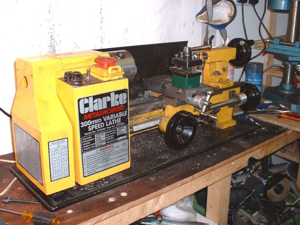
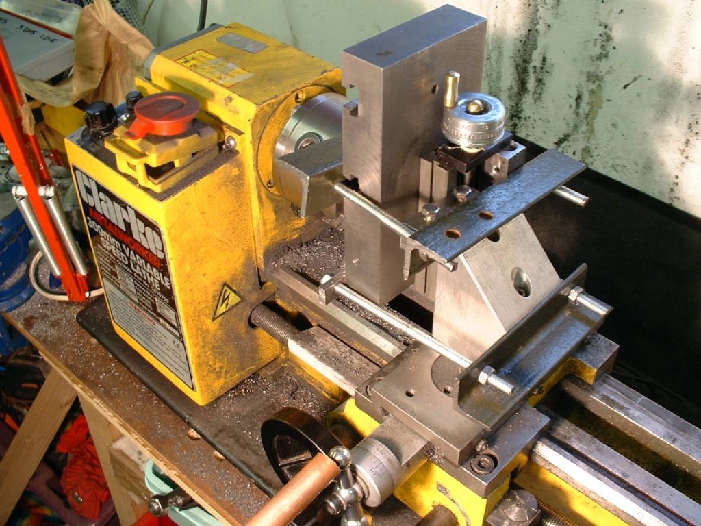
The lathe with its new slide
The ideal material is continuous cast iron; stable, solid but easily machined. The basic shape is a 6 by 3 inch rectangle, but how thick ought it be? This depends on the size of the t-bolts, I originally considered 6mm, as originally used to hold the top-slide in place. On reflection, larger nuts to take advantage of the more robust set-up seemed sensible, so I decided on a ½ inch slot, with a depth of around ½ inch, and ¾ inch as the wide dimension of the slot. A suitable dovetail will take up about ¼ inch, so about 1 inch thick is appropriate to leave ¼ inch of uninterrupted metal is needed beneath the t-slots. So I chose to make three slots, with 2 inches between them. This allows plenty of space to attach the feednut, while ensuring there is one central slot.
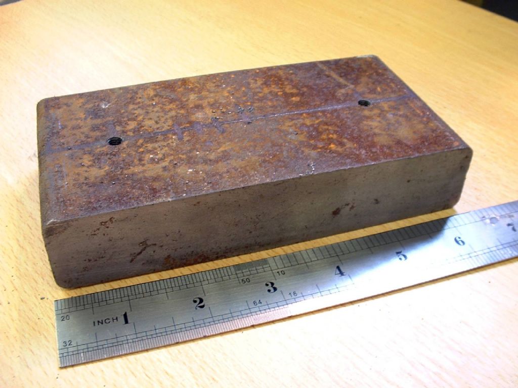
The starting point
After some experience in using the slide, although the slots I used are compatible with my milling machine, I would reconsider having more, smaller, t-slots. This would allow the slide to be a little thinner, though I doubt the increase in the size of work that could be swung over the table would be significant.
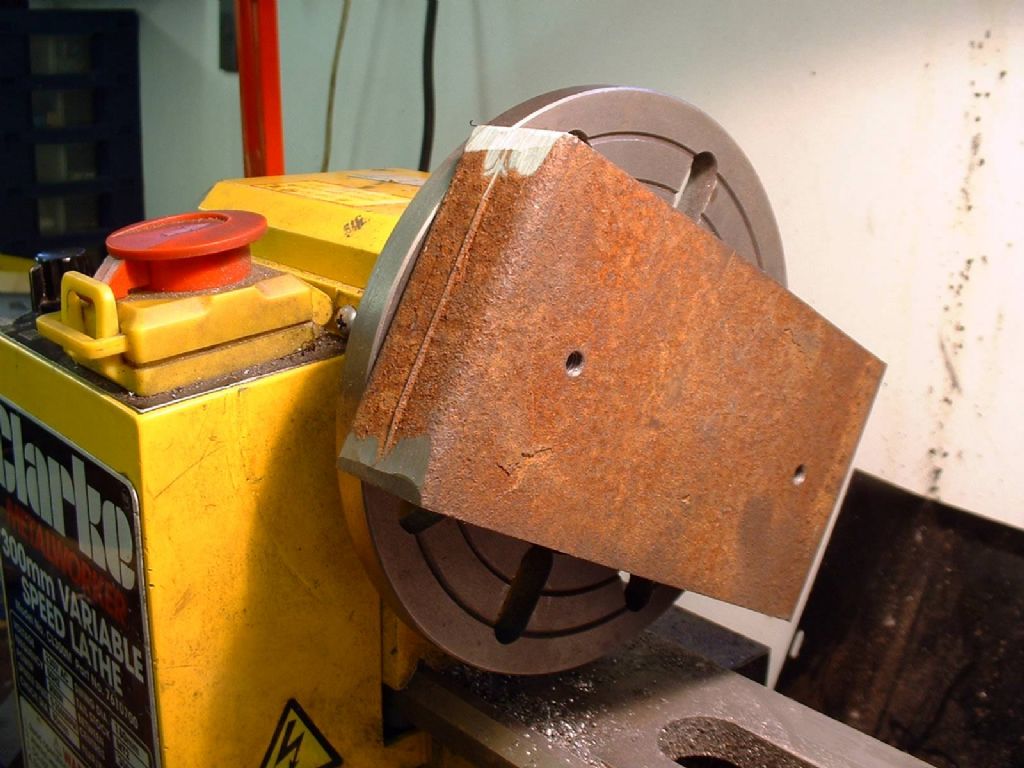
I obtained a 6 ½ x 3 ½ x 1 ¼ inch piece of continuous cast meehanite from College Engineering Supplies. Meehanite is a form of cast iron that is heat treated by being held at a high temperature for a long time, giving it a fine structure and making it much less brittle – ideal for this purpose. I expected a thin slice from a large bar. To my surprise this was cut from a broad flat 3 ½ x 1 ¼ bar, and I was faced with a huge expanse of rough-cast surface. I could have concentrated on making the basic block precisely 3” by 6” by 1”, but I decided dimensional accuracy was less important than getting the six sides of the block square, flat and parallel. I marked the block with a median line, and drilled two 5mm holes 4” apart, and tapped these 6mm on both sides. This allowed me to mount the block on the faceplate and skim the surface. Initially I blew a fuse taking cuts that were a little too deep with an easily blunted HSS tool. A freshly ground tungsten carbide tipped tool proved more effective. With this sharp tool and light cuts, the lathe had no difficulty facing this block at a speed of about 100rpm. In industry a much heavier cut would have been taken to get under the ‘skin’ of the cast block; desirable though this would be, the TCT tool did not seem to suffer unduly from a cut that went in and out of the rough surface. It seems clear that, with a more powerful motor, the lathe would happily deliver much deeper cuts in a material like this.
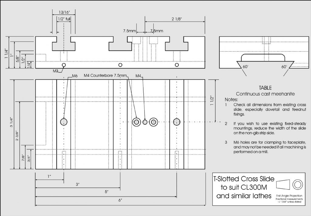
The dimensions of the new slide
The diagonal measurement of the block was over 7 inches. This means it was necessary to bevel the corners with an angle grinder so it could be mounted on 3 ½ inch centre lathe. I also had to machine each surface in two cuts as the feed on the cross-slide is just 3 inches (though the new cross slide solve this, by allowing greater travel). This requires taking the outer cuts with the tool in the outer part of the tool holder, then re-setting the tool in the inner side of the tool holder to machine the central portion. Ensuring the final inner cut moves smoothly from the outer section is easier to do than describe. More difficult is ensuring the final machined surface is flat. Most lathes face a surface slightly concave, to my surprise, my lathe created a convex surface. This actually made my job easier – a straight edge along one radius of the cone left a gap at the far side that I could measure with a feeler gauge. The error was about 8 thou in 6 1/2” as near as dammit 0.00025” in 0.2” (five turns of the feed screw). To get a flat surface I started the final cut at a depth of just 0.002”, and advanced the cut a quarter of a division every five turns. This may sound hit and miss, but 0.00025” was near the surface roughness left by the tool.
A mini-lathe at the limit
I tested the resulting surface on a sheet of plate glass, and it was as flat as I had dared hope. Gentle rubbing over a sheet of fine wet and dry paper over the glass smoothed the machining marks, without completely obscuring them. Perhaps one day I will scrape it truly flat as an exercise in patience! I then replaced the block the other way up and repeated the exercise. The result was a block with the sides measuring parallel to better than 0.001” over 6”. I understand the convexity error was not rare on some early mini-lathes, but long since this time I re-machined the dovetails on the saddle and the lathe now faces very slightly concave.
Machining the long sides was a little more tricky – these were the neatly hacksawn edges of the block, not quite at right angles to the flat surfaces. I drilled and tapped holes where the t-slots would be, and used a thin aluminium shim to compensate for the angle of the cut. Mounted sideways like this the block looked very precarious, but held by just two 6mm bolts I did not get any movement or vibration. I think it is probably very important that I used good quality bolts; I know cheap 6mm studding I have used for other purposes would not have held the block securely. I do not like to think of the consequences of a block this size coming loose, even at low speed!
At first I struggled, setting everything carefully, yet getting a poor result. I had not realised the faceplate itself was slightly concave – sufficiently so to prevent the block being true when set at right angles to the faceplate with a square. I had to shim it with a strip of thin aluminium sheet. It was a case of cut and try, gradually scraping down the thickness of the shim until the cut surface was at right angles to the top and bottom of the slide. Once again a two-stage cut, allowing for the error in the top-slide had to be made. In contrast, machining the top and bottom would be easy!
So, next the short ends had to be machined, and I commenced by rough grinding the skin off the surface, as I chose to use an HSS flycutter. I then removed the tool holder and clamped the block to the top of the top-slide with improvised clamps and two spacers, both 5/8” square. One clamp was bolted tight to the side of the block, the other was ‘floating’. I used a rubber mallet to make sure the block was completely snugged down. The fly cutter happily took cuts 0.040 inch deep at around 200rpm, but with a very gentle feedrate, slowing down at any hint of ‘klunking’. Interestingly, with cuts of less than 0.010 inch the tool rapidly lost its edge, but lasted well with the deeper cuts. The excellent satin finish left by the flycutter was a reward in itself.
Fly cutting one end of he block, note the surface imperfections
It was necessary to shift the work, by swapping over one of the 5/8 inch spacers, to complete each side. By ensuring the block was square with the top-slide, and the top-slide was square to the cross-slide, it was possible to get the short ends at a true right angle in all directions without making any difficult adjustments.
My original plan was to make simple slots with a ¼ inch ‘throwaway’ mill, then open these into t-slots with home-made t-slot cutter made from ½ inch silver steel. I did make this cutter, but as explained earlier I decided to go for larger slots and bought a ready made t-slot cutter. I first opened up the central slot to 1/2, and I took two passes each side using a t-slot cutter to finish to my required dimensions. The final size of slot, means I can make all my own t-nuts by machining down ½ x ¾ inch stock. I can also produce ‘emergency nuts’ for special purposes from ¾ x ¼ inch bar. I have made nuts to suit 6 and 8mm bolts. Now I have an X2 mill with a standard set of t-nuts for 10mm bar, I am pleased to say they are interchangeable with the home made ones.
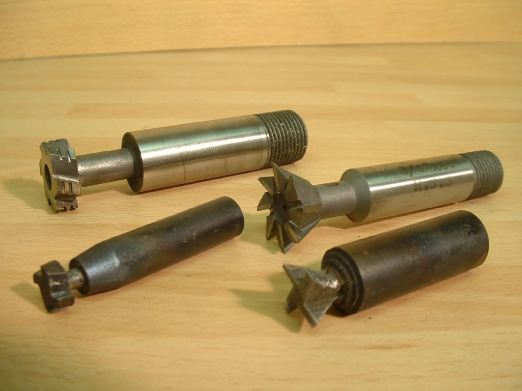
Commercial T and Dovetail cutters with smaller home-made versions
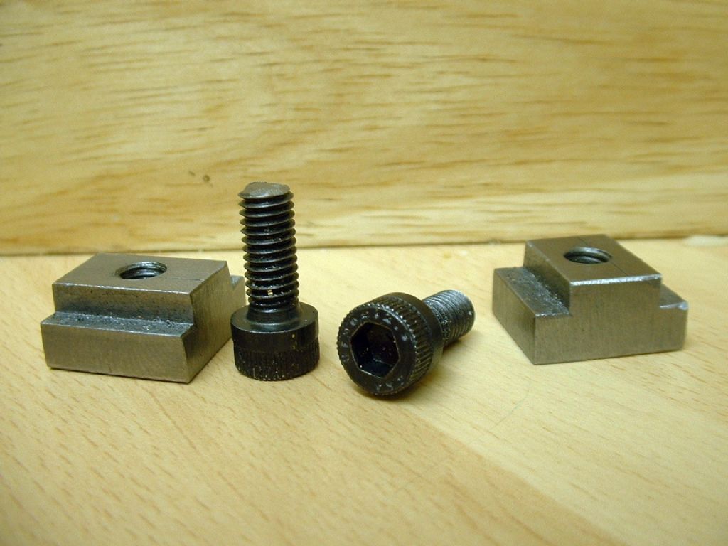
Home-made 6mm t-nuts and stock screws.
I have a light vertical slide, and I clamped the work to this with two strips of angle iron and some 6mm studding. With the gib strips tightened up, it was possible to align the work with a t-square and by measuring from the edge of the work to the slide. The work could then be set vertically, clamping to the base of the slide with a second clamp from another piece of angle and a strip of 3/16 x ½ inch mild steel. As the block was wider than the available cross-feed, a complete t-slot had to be cut in two halves.
Despite the Heath-Robinson appearance, this clamping arrangement worked.
Many, many two-stage cuts later the job was done. The clamping and setting up for each cut took far longer than the cuts themselves. I tidied up the edges of the slots with a fine file, and contemplated the rather scruffy appearance of the bottom of the slots. They were also slightly less than ½ inch deep. Twelve more cuts with the t-slot cutter in three hours on a Saturday afternoon put that right.
Starting a T-slot
I cannot tell a lie! The finish on the bottom of one of the t-slots was marred by some over enthusiastic cutting; this cosmetic blemish was filled with chemical metal, and now it does not look so bad.
I cut the dovetail in three sections. It was essential that the dovetails were parallel to each other. As I was confident in the parallelism of the sides of the block, I worked from them. A piece of hard-surfaced kitchen worktop was cut to lie across the bedways, and flat steel packing used to support the work on top. The work was then bolted to the toolholder using nuts in the t-slots. Assuming the packing stayed put and the saddle was not moved, it should be possible to make half a cut, move the work, and continue the cut without interruption. This may sound hit and miss – I did not expect to succeed first time. In fact the first side appeared perfect.
Roughing a dovetail
I was not happy with the second side. I was unable to align both cuts perfectly, and kept getting a tiny step at the junction of the two cuts. Though under a thousandth of an inch, this would be sufficient to spoil a good bearing. Fortunately, I was able to use the lucky first side as the bearing side and the second became the gib strip side, so I was spared having to hand-scrape the dovetail.
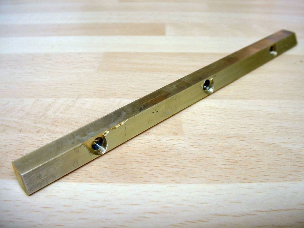
The gib strip was a horrible job. The first tasks were two angled hacksaw cuts 6 1/2” long in 1/4” thick bar of particularly intransigent steel. This was followed by major difficulties with workholding. These were eventually solved by clamping the embryo strip in the new dovetail, using a silver steel bar. I began to feel trapped in a Chuck cartoon, as I drilled, filed, ground, milled, sawed and cursed two 60° facets on the bar. At one point I swear I considered trying to bolt the strip to the faceplate at an angle and facing it! Despite all these tribulations, I eventually got a suitable shaped strip and then set about polishing the rubbing face of the strip on a sheet of wet and dry paper over glass. This eventually gave a decent finish to the bar, but combined with a poor job of drilling locating dimples for the adjusting screws, I had trouble getting a good result. The adjusting screws caused the strip to twist away, rather than contact the dovetail smoothly. Initial trials with this steel gib strip were not perfect. On a test cut facing across a 1/2 inch mild steel bar I was able to take a 1/16 inch deep cut as rapidly as I could turn the handle. I tried a 1/8 inch cut, it was slower and there was some chatter, but I think this was more to do with a poor tool profile. This was good, but to get the slide rigid, the gib had to be far too tight.
Taking a 1/16 inch facing cut
I had to admit this steel gib was ‘unfit for purpose’, and started from scratch with a piece of 1/4” thick hard brass. I was worried about using an inferior material, but I note that brass gib strips for mini-lathes have now become available as an ‘upgrade’. This brass was some material I had obtained to make a worm-wheel for a rotary table. I had found it awful to work, and after three failures at wheel cutting I gave up, obtained some leaded CZ160 and found immediate success, but that’s another story. I reasoned that its hardness should make it ideal for a gib strip. Suffice to say that it took two evenings of milling, sawing, filing and swearing to produce the second strip. I began to wonder if this was some exotic alloy of copper and tungsten, or if making a gib strip was an insult against the Gods of metalworking (Thor?).
The brass gib strip
This time I took more effort to ensure the strip virtually filled the available space, to minimise the chance of twisting. It still didn’t work, but after much contemplation and deriving my own theory of gib-strip geometry, I realised that the point of action of the gib adjusting screws had to be below a line bisecting the corner on which the strip was pivoting. I milled three suitably positioned flats, then drilled 3mm blind holes to take the end of the adjustment screws. Success! The still mirror-finished bearing surface of the strip was lightly honed on the trusty wet and dry paper over glass, just enough to give an oil-holding matt finish.
I had a spare feednut, as the original nut on my lathe came ‘equipped’ with a stripped adjuster thread. This was repaired by silver soldering a steel insert into the bronze nut, and as this had worked, I had never got around to fitting the new nut. I also milled (with the table attached to the toolpost once more) a recess to allow the larger slide to move over the index. In order to maximise the available travel, I hand filed the end of the feednut to be an easy fit in the round end of the slot for the feedscrew. The combination of these two actions added rather more than ½ inch to the travel. It is now possible to face a full 7 inches diameter in one go.
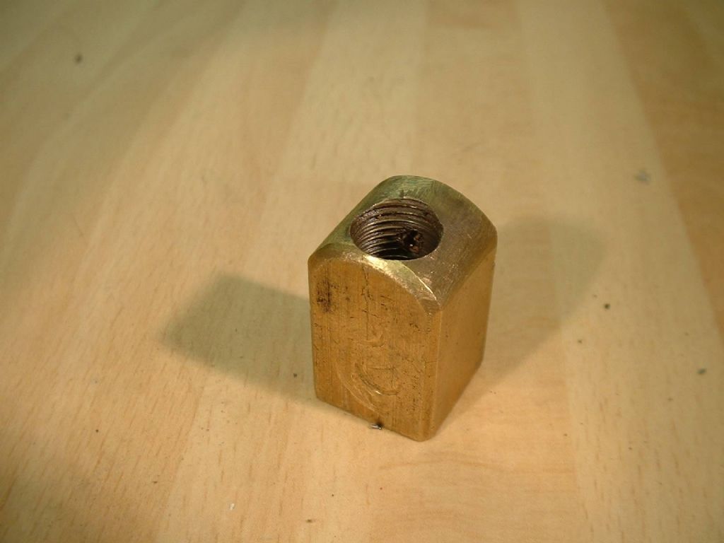
The modified feed nut.
In use, I found that the new slide was smooth to use yet the heavy trial cuts with the steel gib could be repeated. As long as the leadscrew clasp nut was held closed accurate milling was possible, giving an excellent finish, even with my light vertical slide. Perhaps the most surprising change was when I decided to take a very light, fast facing cut on a 2” diameter disc of mild steel. With the lathe running at about 900 RPM and a depth of 0.002” the swarf came off like cotton wool. The ability to increase rates of metal removal, yet also take such light, accurate cuts is a real boon.
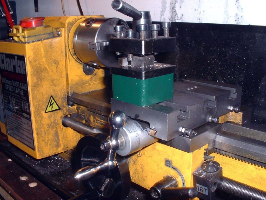
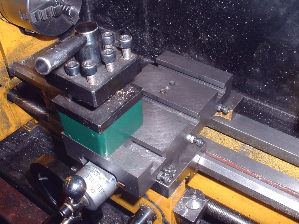
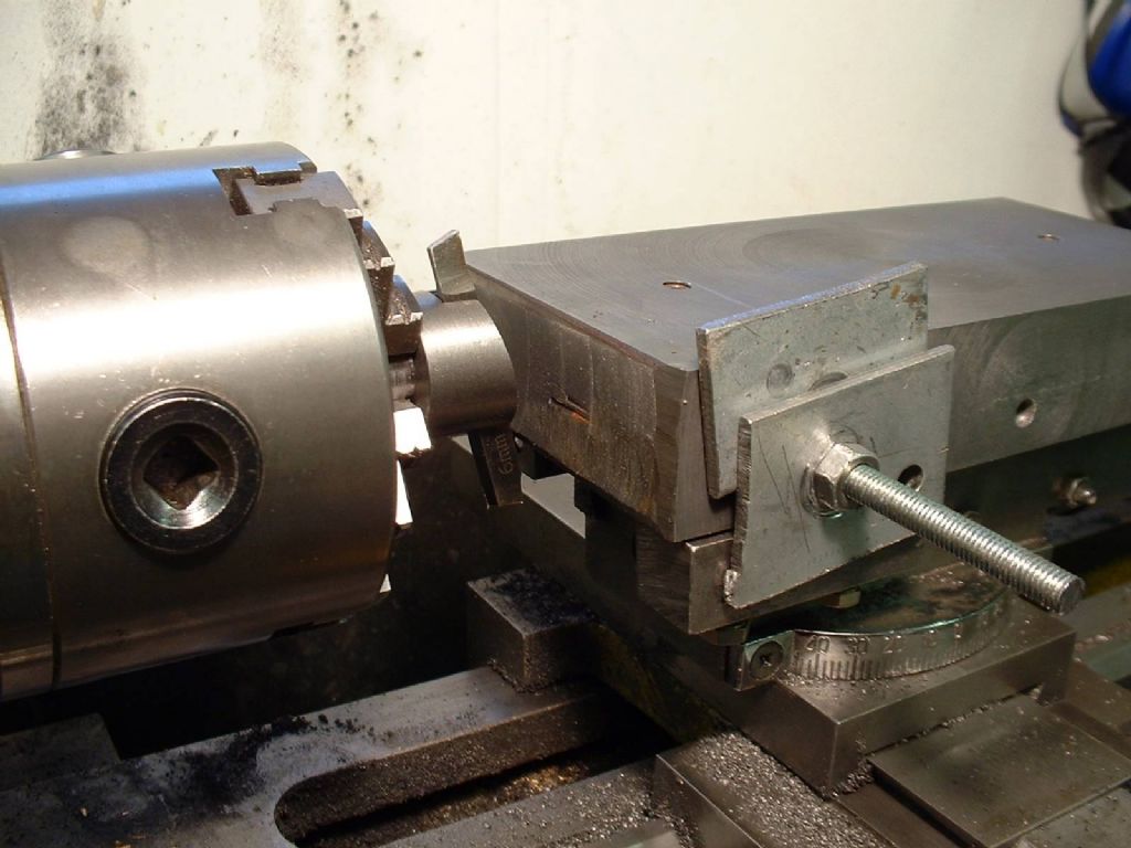
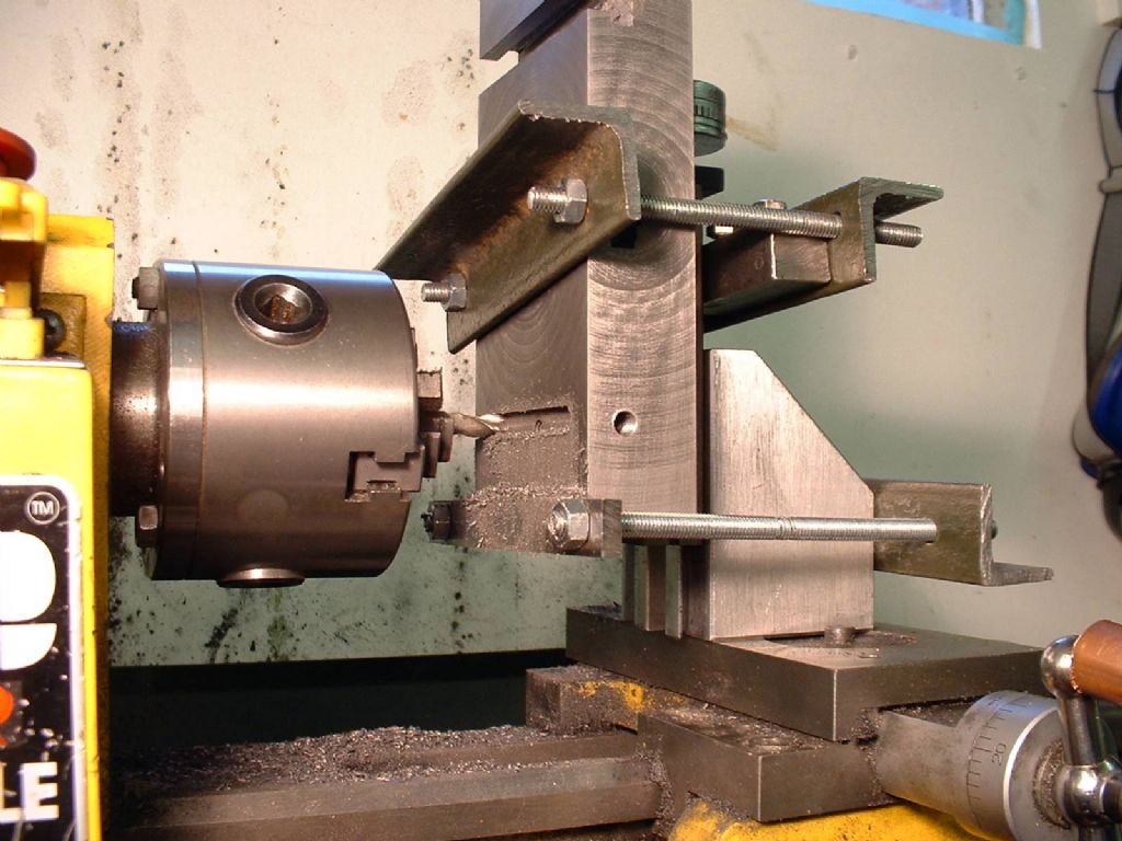
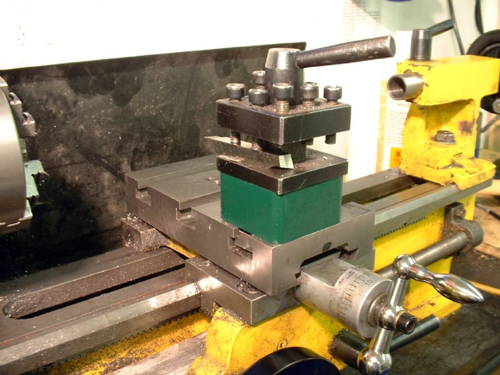
The new slide and toolpost fitted to the lathe
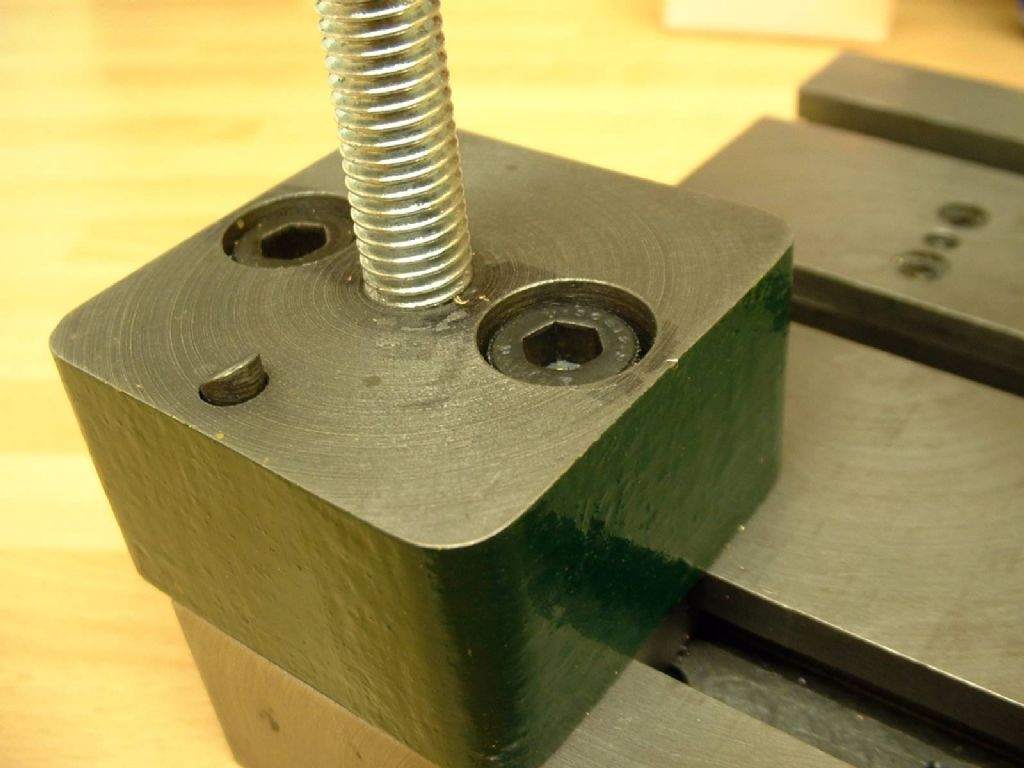
To complement the table, a replacement toolpost is required. I made mine from a section of 2” square continuous cast iron, complete with a detent for the toolholder. It is held in place by a ‘double’ t-nut. This is a straightforward task and the drawings ought to be sufficient guide on their own. One tip is to ‘flare out’ the end of the detent spring, so that it holds itself in its hole if (when) you turn the toolpost upside-down.
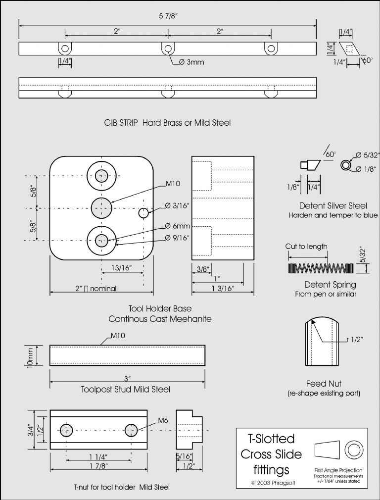
Dimensions for the toolpost and gib
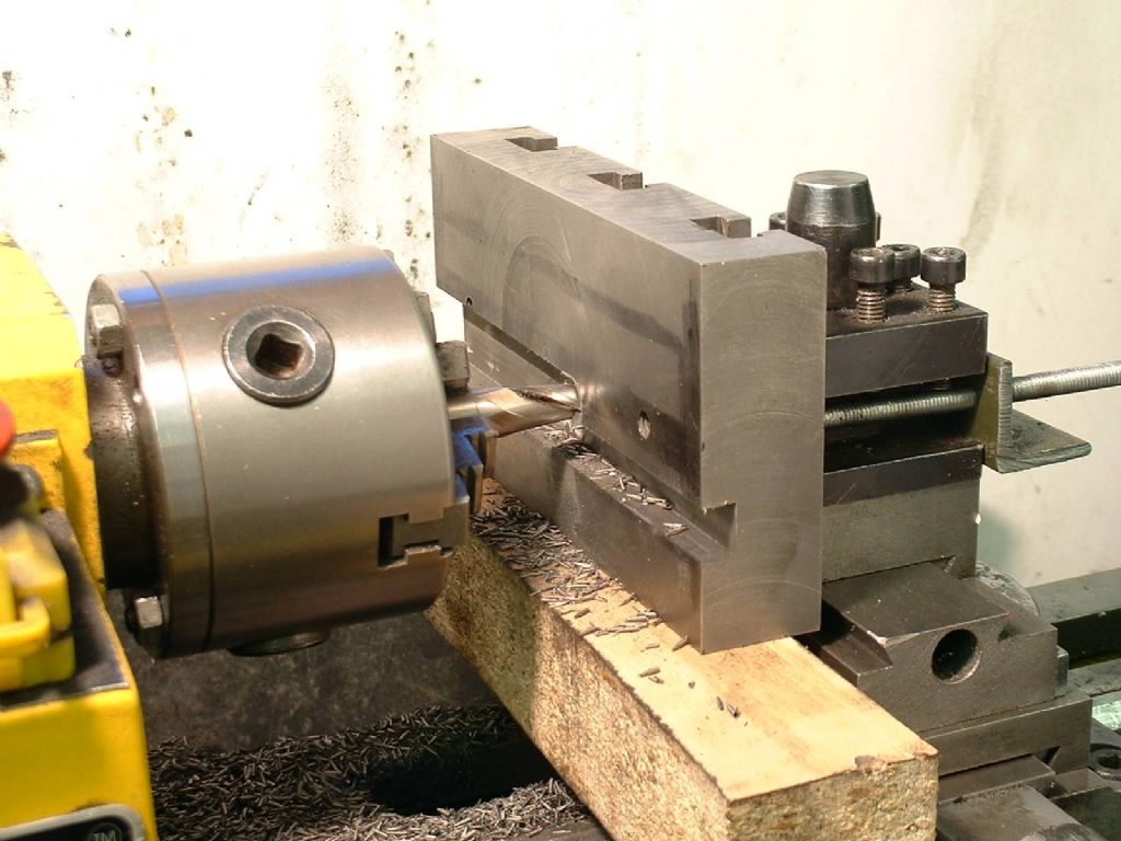
New toolpost in place
All in all, I consider the combination of rigidity, extra travel and the ability to attach different accessories quickly and easily has taken the lathe a long way along the road to being a truly professional piece of equipment. I am the first to admit that the finish is not 100% perfect, but what matters is that it is as true as I can measure it, rigid and works smoothly and accurately. Perhaps one day I could scrape it all over, but I doubt it would work any better. My only caveat is that, if you wish to follow my example – don’t. Make your table on a vertical mill, it will be easier, quicker and probably more accurate.
Aother view of the lathe with the new slide fitted
Neil Wyatt


