Peter Seymour-Howell builds a new workshop before continuing work on Flying Scotsman.
I wondered if the building of a new workshop for the construction of Flying Scotsman might be of interest to other model engineers? Since I can’t progress any further with the model itself – until, that is, I have somewhere to actually build it – I thought that a description of the build might be of interest to others in a similar position.
I will cover the materials used and also my approach to each part as well as giving the general layout. I’ll also be using a lot of recycled materials in an effort to keep the costs down which in this current ‘cost of living’ crisis may be of some use to others.
Enjoy more Model Engineer Magazine reading.
Click here to subscribe & save.
When building the locomotive I took a lot of photographs, and I’ll also share photographs here as I feel seeing what’s actually happening helps greatly when trying to describe something and saves on the text.
Background
A little background may be prudent. As explained before I’ve had a few health issues – that and the fact that my wife and I had been telling ourselves for some years to sell up and do what we always wanted, to live in a village away from all the stress of the inner city. Now that all of the kids have moved on with their own families there was nothing left to hold us back and so we have now moved to a lovely village in Bedfordshire. My only regret is that we didn’t do this decades ago.
So, what ideas did I have for my new place of work? First of all, I now have easy access to the workshop, as the old place had no rear or side access, which is a bit problematic when trying to get a heavy live steam locomotive through the house, especially as the years roll on with my aging body. With this in mind, I looked for a suitable property to fit my needs. My wife was amazing because she understood how important the workshop was to me and so properties without the necessary features were quickly dismissed, no matter how nice they may have been.
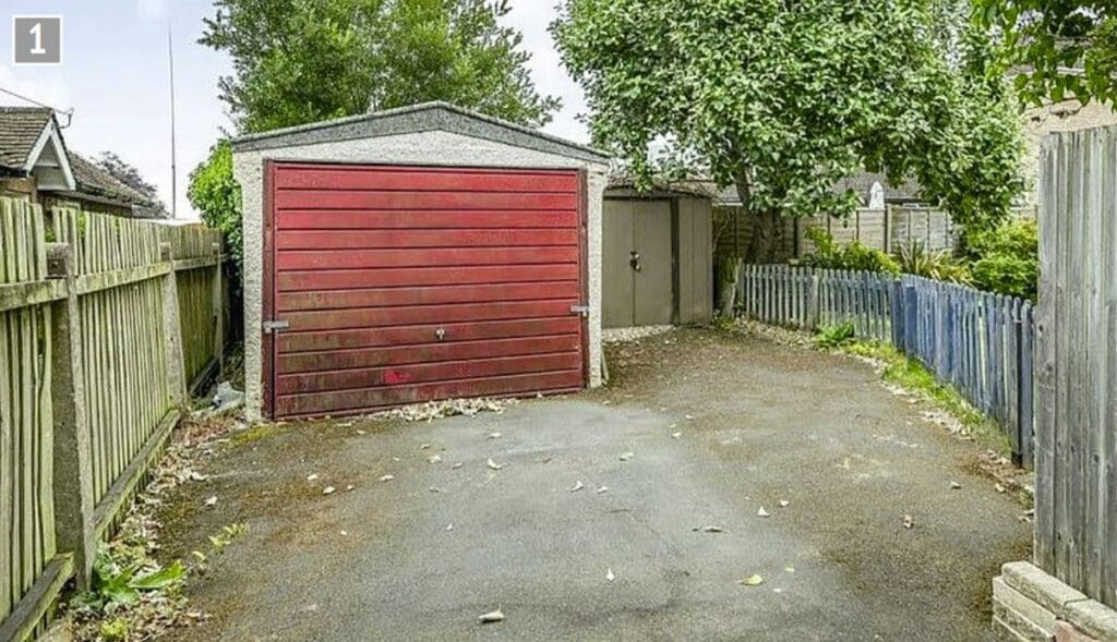
Enough of that, let’s get on to the area where the workshop is to be built. This picture (photo 1) is one the estate agent took, and shows the state of things before I touched anything. We see a concrete garage, which is positioned at the bottom of the rear garden, and a good-sized tarmac hardstanding accessed through a double gate. There is also a metal shed and a picket fence to separate the hard standing from the garden lawn. The metal shed will be disposed of but for now will be used to house non-perishable goods.
The biggest headache for this exercise is trying to protect the workshop tools while building the new unit. I decided early on that I would keep the garage in its original position and extend it to the left side as seen here, basically where the metal shed sits. The asbestos roof had to go and the roof pitch would also be raised a little.
My very first workshop was of the same construction before later building another next to it in timber and what I learned from those two units would be put to good practice here. Most importantly for the garage is to make it warm with good insulation and damp free; for this reason, the perfectly good asbestos roof had to go – more on that later. The easiest and cheapest way to extend the concrete panels is to get more panels to add to them and these can be found surprisingly cheaply as I will show.
Donor garage
First, I needed the panels. I searched a number of sites with prices ranging from £10 to £130 (new) per panel. If you take a look you will also come across free panels as many are given away, so keep an eye out if doing the same as I was.
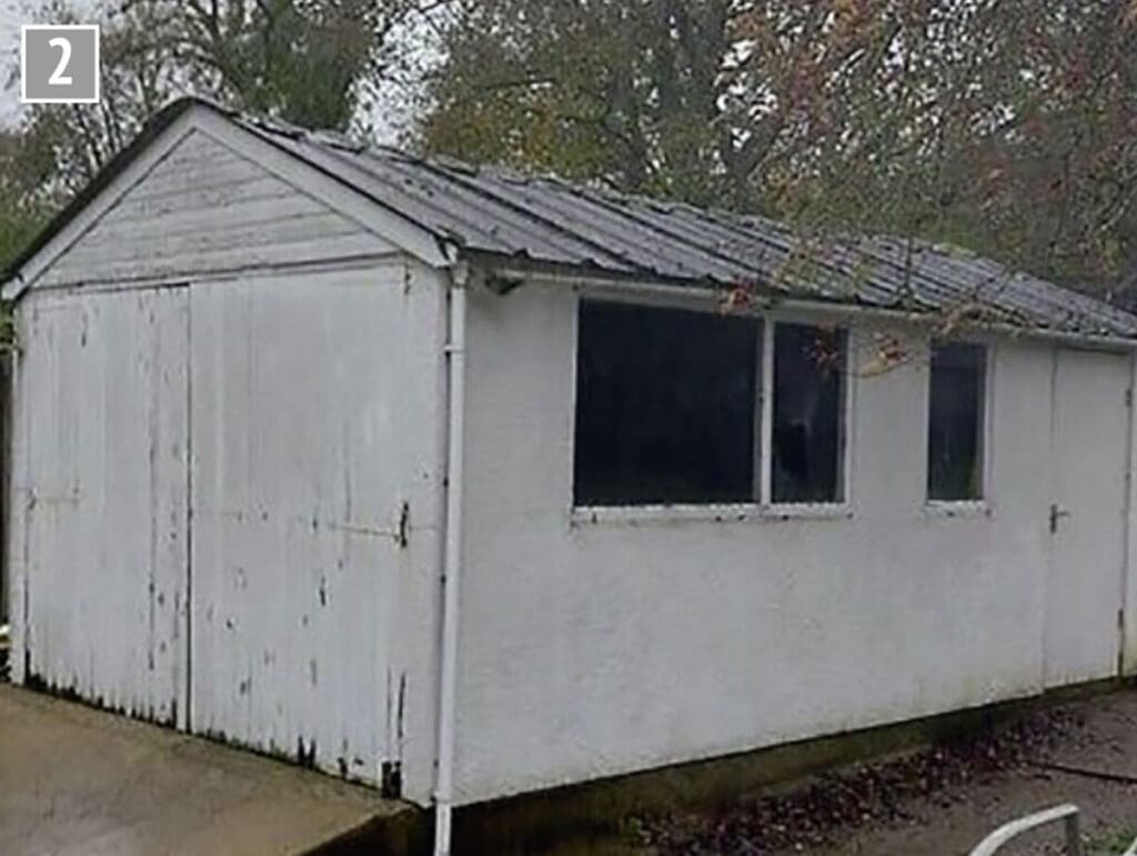
I got lucky and spotted a complete garage on that well-known auction site with no reserve and, better still, the asbestos roof had already been disposed of properly. The only issue was the unit needed to be dismantled and taken away.
After checking with family if they could help and arrange transport I put a cheeky bid in and waited for the auction to end. I did try to get the seller to tell me how much he wanted to make an offer but he wanted to let the auction run – fair enough, I often do the same.
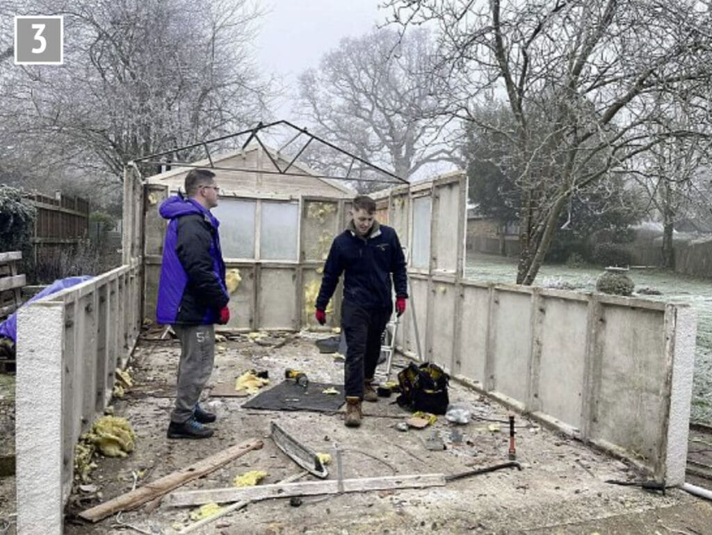
Photograph 2 shows the garage that I won for the crazy price of 99p – I’m so glad that I didn’t make an offer… You see the roof here but that was already off when my boys went to collect. Here (photo 3) is a snapshot of the lads in action, one son on the left, grandson on the right, and another son who took the picture. I couldn’t help having had two bad falls during the move and thus confined to light duties. The panels themselves are in very good condition as are those in the garage at the new place, all boding well for the future.
Preparation
With the donor garage sorted I could move on to preparing the ground for the new extension which I require to allow for more space – lessons gained from the lack of space in the old one as new tools were added over the years. I also wanted to allow room for more tools in the future and, most importantly, a door large enough for bigger machines if I ever get lucky enough to own one. The old place only had a standard household sized door.
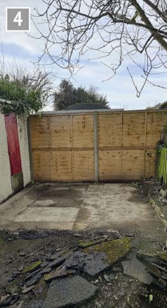
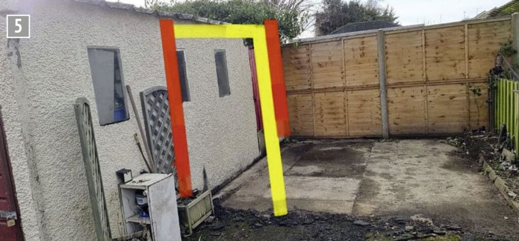
I began by moving the metal shed from beside the garage and dug up the tarmac that had been underneath. It was good to discover that beneath the tarmac was a layer of concrete which is more than good enough to build the extension on. Photograph 4 shows the area after the tarmac had been cleared showing the concrete base, not level but strong enough to build on. I used a similar picture (photo 5) to plot out my plan for the new building and how it would connect to the old. The red lines show how much of the existing garage needs to be removed and the yellow is approximately where a small door will be fitted.
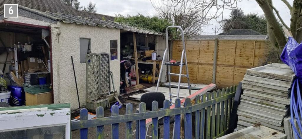
The next job was to remove the superfluous panels to make the resulting building a one piece ‘L’ shaped unit. This involved removing four panels plus the door to give an opening of just over three metres. Note that a length of timber has been used to keep the roof up and also that the donor garage is now on-site awaiting erection. As you can see from this picture (photo 6) the garage is very full which makes things a little more difficult, trying to work around everything.
The extension
It was then time to start the build. The ground was checked for how level it was and we were happy to see that the ground sloped gently away from the existing building. The reason for being happy is that it’s easier when working from the existing building to build up the deficit in height using plastic spacers prior to a mortar mix being placed around/under the new panels.
A couple of things to point out – the existing panels (one piece) are slightly higher (25mm) than the donor half panels that come out at two metres when fitted on top of each other (these are also wider but none of this matters), nor does it matter that the bolt holes to join the panels are spaced differently. The reason that these differences aren’t a problem is that the two types of panels will be joined together using 6 inch square treated fence posts.
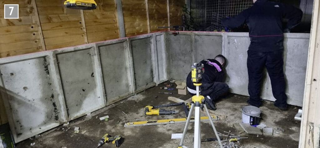
Photograph 7 shows the bottom layer of panels being erected. You can see the packing used under them and just in view to the left is one of the fence posts already bolted to the existing building and the new panels bolted to it. The process followed was to bolt up the first panel checking for height so that when the next panel is set on top it aligns with the existing top.
We then bolted each subsequent panel to the previous keeping everything level with the use of a laser level, remembering to fit the corner panels at the right time. You can see the laser running along the top of the panels.
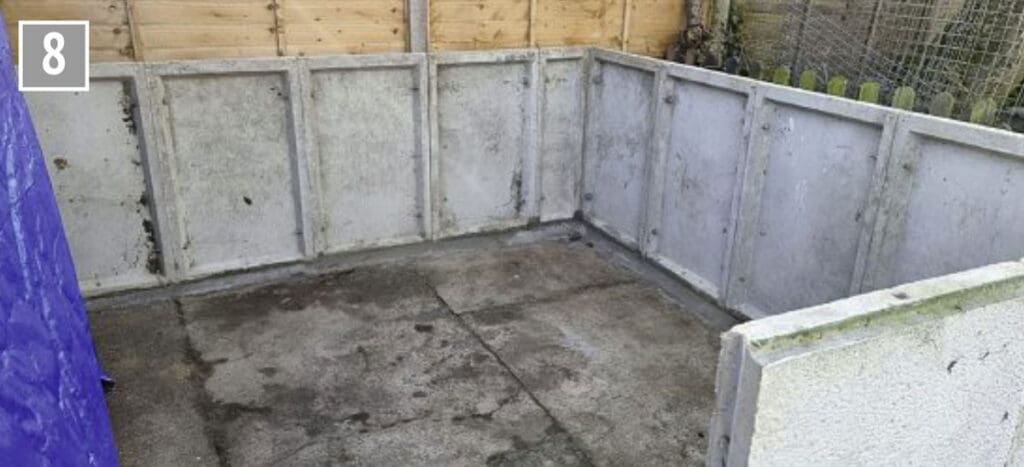
Photograph 8 shows the panels the next morning after the mortar had been laid, which you need to leave a few days before doing the next stage, which for me would be installing the next layer of panels. This picture helps show the mortar, which gets thicker to the right, and also the bolts which join the panels together. There are also bolt holes in the middle of the top and bottom webs for bolting the next layer.
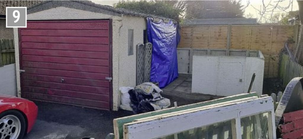
The last picture for now (photo 9) shows the general layout so far, which gives a good idea of the size – the new section is approximately three metres square.


