Last month, I was sacked and was without a job. I had to get another job and fast. No money coming in was not an option. I managed to get a job as a stores person in a press shop. What I did not know was that they really wanted a labourer although they already had an odd job man/ labourer. Still, it was a job and the money was the same as the last job, £7 a week before tax. I had to pay my mother and also the bus fare to work. One of the main things I had to do was to barrel some of the finished parts; most parts that are pressed out are sharp and some of them needed the burrs removing. The tumbling barrel was a large barrel about 2 foot diameter that rotated and could be tilted from well above horizontal when running to below horizontal when all the components would fall out into a parts bin.
A long running job was the manufacture of the tops of car shock absorbers for the Armstrong Patents company. We produced many thousands of these components a week. They were sawn off on an automatic saw and then I had to wheel them on a sack truck from one factory to another for tumbling. Unlike the majority of the components, these were not barrelled dry; they were barrelled in paraffin to wash them as well as to deburr them. If you want to know what cold is, try putting your hands into freezing cold paraffin on a crisp winters morning.
A press shop uses a lot more metal than a conventional machine shop and it was not unusual to have 3 or 4 lorries to unload, one at each of the doors. Then everybody had to get stuck in and unload the lorries, a task the highly skilled toolmakers did not like. The tube came in at 20 feet long lengths of about 12 tons at a time and it all had to be unloaded by hand. Not nice in the winter but great in the summer sunshine. The other lorries usually had several tons of steel on as well, some as guillotined strip and more as steel coils.
The boss wanted the barrel moved to the other factory to save wheeling the components between the factories. The other labourer was given this job; he was a lot older than me, probably about 60 and had a better idea of moving machines than I had at this time.
It was about a week before Christmas and the barrel move was almost complete. It was quite cold and I was surprised to see the labourer wandering around the factory minus his overall, his shirt and his vest. It turned out that when rebuilding the barrel he had lost the grub screw that held the counterbalance weight on the barrel. No problem, he had replaced it with a long Allen screw. Unfortunately his overall had caught on the Allen screw and it had been pulled off together with his shirt and vest. He spent all of the next week including Christmas in hospital. This is another example of rule two, keep away from moving machinery, being ignored.
I had held this job for quite a while and enjoyed doing it although always sought more experience. I did quite a bit of tube bending making parts for motorcycles particularly leg shield and pannier parts for AA motorbikes. After bending, the tubes had to be stove enamelled in a large oven. This stunk the whole factory out and I was not popular when doing this activity.
I often helping out setting a power press under supervision although still below the legal age limit (16) for doing this. This was an activity I enjoyed although I still had to do my main job. More next time unless I get lots of complaints.
Installing and aligning a lathe
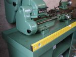
A Myford ML7R lathe is a very heavy item. Although two people can lift it, an engine hoist is a better bet. It needs to be lifted off the bench or Myford stand and prepared for transport. First, separate the lathe from the stand making sure the machine is unplugged or disconnected. A Myford is very unstable when unbolted as the motor makes it back heavy and it will try to topple over. The best way to stop this is to bolt two lengths of wood through the mounting holes. The wood needs to extend behind the lathe so it cant roll over.
The lathe will be heavier at the headstock end so it would help if a couple of people could steady the lathe while it is being lifted. The lathe (and cabinet if there is one) should fit nicely into a reasonable size estate car.
Article continues below…
Enjoy more Model Engineer Magazine reading.
Click here to subscribe & save.
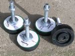
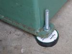
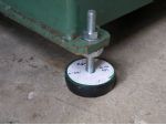
Now you have got your new lathe home, it needs to be installed and levelled correctly. I have used special machine mounts supplied by J&L Industrial. These have a thick rubber pad with a threaded rod in them. The nut that goes under the lathe stand is quite large and the stand is secured with a smaller nut on the top. I wanted the stand to tilt slightly towards the tailstock end and also towards the front. This would enable the spindle and cutting oil to flow to the front left corner of the tray.
The feet had the bottom nuts set to about 2mm above the rubber pad as a starting point. The lathe was pushed back to tilt it and the feet were installed at the front then the lathe tilted forward and the back feet were fitted, photo 3. This is a two person job, one to tilt the lathe and the other to fit the feet.

Article continues below…
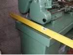
The lathe was then moved to its final position in the workshop. A spirit level was put on the front of the stand. The stand was tilting towards the headstock end so the front right foot lower nut was turned until the stand tilted towards the tailstock end then the rear right nut was raised to match. This required quite a bit of movement. All four feet were then tweaked so that the lathe was rock steady with the right front of the stand slightly lower than the rest. The final job was to tighten the top foot nuts down.
Article continues below…
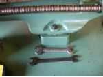
Now with the stand level, it was time to align the lathe. Assuming you are using the proper Myford raising blocks the first thing to do is to make sure the mounting studs are flush with the end of the nut underneath the top of the stand. Adjust if necessary and tighten the nut against the bottom of the stand. Sometimes, when removing or replacing the lathe on the studs, the threads can get damaged stopping the nuts from screwing onto the studs. Tightening the nut against the bottom of the stand makes it easier to start the nuts on the
top.
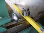
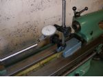
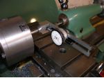
Lightly tighten up the two headstock securing nuts and check that the lathe is level across the bed. (The chuck is there to stop the level falling off the bed.) Adjust as necessary using the adjusters in the mounting block. Then place the spirit level along the bed and adjust the tailstock end until the bed is square. Slacken off all four nuts slightly. Put a length of bar into the chuck and set up a test indicator on the tailstock end. The three-jaw chuck will be fine as no great accuracy is needed. I used a self centering four-jaw chuck as it was the first that came to hand. Tighten the front left nut down. The indicator should not move. Tighten the rear left nut followed by the front right nut and again the indicator should not move. Finally tighten the back right nut again with no movement. If at any point you do get a movement, tweak the relevant adjustable foot below the lathe bed and tighten the nut again.
When all is finished, put the dial indicator on the front of the bar, slacken then tighten both of the tailstock nuts checking for no movement. If there is a movement, tweak in the required direction and check again on both the top and side of the bar.
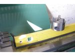
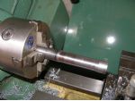
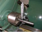
Put a piece of bar about 3/4in. or 19mm in the chuck and relieve the centre. Move the bar out a bit so you can get at both ends of the bar. Take a light cut at both of the proud portions then take a finishing cut of about 1 thou, (2 thou on diameter) and check that both ends of the bar are the same size. The first time I checked, I got a variation of 2 thou on diameter. I cleaned the bar and checked the micrometer using the ratchet. Using the ratchet was causing the problem. Not having used the micrometer for over twelve months the spindle had got a bit sticky. I got two more micrometers from storage but they were the same. A quick squirt with WD40 and the micrometer was free running again. I rechecked the bar at both ends and it was as close to parallel as makes no difference.
Article continues below…
The tailstock was next to receive attention. I used a centre finding test indicator but any ordinary indicator would do. The tailstock was locked up and the indicator was adjusted to zero in the tailstock bore. The tailstock was then adjusted so the bore was reading zero at the front and back. It might need adjusting slightly when turning between centres but should be fine for drilling as it is.
The forward/ reversing switch has had a round knob fitted. This is because I have, on a couple of occasions, knocked the switch on when it was operated by a lever. This is not a major problem as the clutch was disengaged but it was still thought to be a necessary safety modification. I do have a no volts switch to fit but have not had time to fit it yet. I will fit it before I start any machining jobs. Next time, a simple bed stop and a carriage lock for the Myford.
J&L industrial, 7 Pacific Avenue, Wednesbury, West Midlands, WS10 7WP.
Free Phone 0800 66 33 55
www.jlindustrial.co.uk
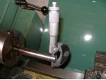
 The tailstock was next to receive attention. I used a centre finding test indicator but any ordinary indicator would do. The tailstock was locked up and the indicator was adjusted to zero in the tailstock bore. The tailstock was then adjusted so the bore was reading zero at the front and back. It might need adjusting slightly when turning between centres but should be fine for drilling as it is.
  The forward/ reversing switch has had a round knob fitted. This is because I have, on a couple of occasions, knocked the switch on when it was operated by a lever. This is not a major problem as the clutch was disengaged but it was still thought to be a necessary safety modification. I do have a no volts switch to fit but have not had time to fit it yet. I will fit it before I start any machining jobs. Next time, a simple bed stop and a carriage lock for the Myford.

