Background
There are many occasions when it becomes necessary to graduate various scales on pieces of workshop equipment and projects. There have been various ways of achieving this described in the past, which have been effective and produced successful results.

Although there are usually no time constraints in the hobby workshop, anything, which produces the results quickly and fuss free is worthy of consideration. The Graduating Tool supplied by Hemingway kits is one such item, photo 1.
Enjoy more Model Engineer Magazine reading.
Click here to subscribe & save.

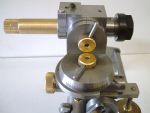
This assembly is fitted to a back-plate with spacers to clear the operating lever and is attached to the clamping bar to be gripped in the tool post, photo 2. The clamping bar is positioned to place the tool tip on centre height each time it is mounted on the lathe.


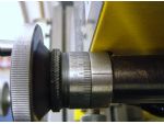
A turret is mounted on top of the body as in photo 4 and the grub screw at the zero position compresses a spring against a steel ball engaging indents in the body to select the turret positions. The turret is marked with the 10’s and the 5’s positions either side of the unit position for ease of operation.

A split bracket containing a silver steel depth stop is clamped to the ram, photo 5. The stop engages in holes in the turret, which are drilled to the required depths representing the three line lengths. Obviously, when the line length ratio is decided upon, this ratio is fixed. I have found that if longer unit lines are required, the zero is set from the end of the work-piece as normal, then the tool moved along a distance equal to the extra length required and the stop locked at this position, giving longer unit lines with the same length ratio of the 5 and 10 lines, which doesn’t seem to be out of place, as shown later.
Using the Tool


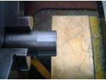
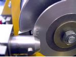
With a depth of cut set to 0.05mm and the 10’s position set on the turret, the first line is made and the turret immediately set to 1. Counting is easy as you count to four and set the turret to 5, make the line and immediately return to 1 and count to four again. If the rotation of the piece is arranged to be anticlockwise, the progress is easily observed and it will be obvious which way to click the turret, i.e. 5 or 10, photo 7.


If the facility to accurately locate number stamps in the lathe is available, then the numbering can be done now or in a suitable fixture later. Before removing or parting off the work, bring a fine finishing tool, photo 8 up to just touch the surface, which will apply the finest of cuts. Skim over the surface removing the burrs from the lines and the curls at the ends. No further finishing is required using this tool, photo 9.
Final Touches
If the scale is gone over with a chinagraph pencil, then rubbed over with a drop of oil on the finger, the lines will show up quite well after the resulting mess is wiped off with a paper towel, photo 10.
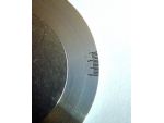
When cold, I went over the polished scale with the piece of wet & dry to remove the oxide coating, and the lines and numbers were permanently blackened, photo 11. The polishing is necessary, as any slight scratch or tool mark will also be black when completed!
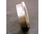
Due to the symmetry of the ram, it is possible to mount the cutting tool in either end and mount the tool across the lathe axis to form scales on the face of a disc, photo 12. These 15deg. marks at the edge of a 70mm dia. disc were coloured in the same way after a fine facing cut, photo 13.
The versatility is such, that if the cross slide travel won’t accommodate a large diameter work piece, then the stop bracket and the tool can be mounted on the same end of the ram, gaining the length of the body. Also mounting both items in this way, the tool can be pulled making the graduations from the inside of a disc.
Put to Use
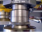
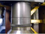
My cross slide dial was marked with 50 divisions as in photo 14 giving 0.02mm per division. I thought it would be a good idea to have 100 divisions reading 0.01mm and made a new dial, photo 15. I also made a vernier ring, not that I particularly wanted to read to a thousandth of a millimetre, but to see if it was possible to make one with my change wheels.
The little ball handle at the top right is a hand wheel lock as per GHT’s writings, which I hadn’t given much thought to until I was taking the final cuts in the bore of the Worden table sliding block and felt a final pass to remove the spring in the tool should do it.