
Enjoy more Model Engineer Magazine reading.
Click here to subscribe & save.

To start the KX spindle, type 600 into the lower speed box on the program run screen and press enter. The spindle will only start when you click on the spindle start icon or press F5. To stop the spindle you do a repeat of the same command.
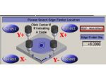
First reference the Y axis. Jog to the edge of the work or vise until the edge finder clicks out. You can jog by pressing the tab key on the PC keyboard. The jogging tool fly out will appear on the right of the machine. To remove the jogging fly out, press tab again. At this point, click in the Y axis DRO box and type in the radius of the edge finder. If the edge finder is in front of the work enter the edge finder radius as a negative value and press enter to have it accept this value. If the edge finder is at the rear of the work, enter a plus figure.
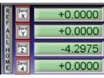
Next raise the Z axis using the page up button so that the distance between the top of the work /vise and the bottom of the spindle is greater than the distance from the bottom of the longest tool to the bottom of the spindle, i.e. you need clearance between the bottom of the longest tool and the work. A decent figure here is 30mm as this will clear most clamps etc. This is known as the clearance plane. We now Zero Z at this point with the Z Zero button on the readout.
If you have a spare tool holder, I suggest you put a bit of bar longer than the longest tool in it and use this together with a block of metal say about 30mm thick to set the Zero. Then if you need to reset, all you have to do to set the Z is to bring this bar back down onto the setting block and you can Zero the machine Z so avoiding the need to set all the tool heights again.
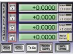
To then Zero X and Y we press the GOTOZ button then the ref all home button then Zero X,Y and Z again so all the DRO’s read Zero. This now sets the machine coordinate and work coordinate points at the same position as your work Zero. The important thing is that both sets of coordinates are set to Zero. You can check this by clicking on the machine coordinate button. It will alternate between machine Zero and coordinate Zero. If they are not the same, repeat the previous section until they are.

Jog the tool down using the page down key until it just touches the work. A time honoured method here is to use a sheet of cigarette paper under the tool until it just traps it. At this point click the set tool offset button. Note – ensure the gauge block box is set to Zero.
This then enters the value in the tool table. If you now click the Tool offsets option to on (the surround turns green) the Z readout will show Zero. Click the machine coordinates button and you will see that the Z reads the same as the tool offset. Click the machine coordinates button again so it is no longer red. If you now click the Tool offsets button again to turn it off, The Z display changes to the actual Z position.
Go to the Program run screen and click the GOTOZ button and the tool will raise to the preset Z clearance plane. Repeat for all the other tools you are using in the program.
At this point, all the work and tool offsets have been set. Go to the offsets screen and save the tool offsets. This table will load when you next switch the machine on. All work offsets in the work offset table should be set to Zero. Before finishing the machining session, change to tool 0, (no offset) and press the GOTO Z button. Next time you switch the machine on, Zero it where it is and you should not have to wobble the component in or set the tool heights again.
That concludes this section on setting Zeros and tool heights without using the G54.
Last month, we set the X & Y positions with G54. Before setting the tool heights, we need to set the Z height. We need a dummy tool to do this, put the tool into the spindle and bring it down to the top of the job. If possible, make the dummy tool longer than any of the tools used on the job. Make sure that no tool offsets are active by changing to Tool 0 on the offset screen. Click on the Set Z button after checking that gauge block is set to Zero. This will put the current spindle position into G54. All tools will be offset from this point.
Put tool 1 into the spindle and take it down to touch the top of the job. Change the tool No display to tool 1 and click the Set Tool Offset button. Enter tool diameter if required and press return. Tool 1 is now set. Repeat for the remaining tools. If you ever need to reset a tool, perhaps due to breakage, just change the tool No to 0, put the dummy tool into the spindle, bring it down to the top of the job and Zero the Z display. (The Machine Coords button should not be red.) Change to the new tool and set the tool number to the replacement tool. Bring this tool down to the top of the job and click Set Tool Offset. The replacement tool is now set. You should now know how to set Zero and set the tool heights using the two different methods.


