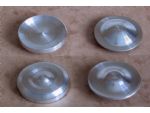
A recent project required a number of caps similar in style to hubcaps and rather than having a plain surface, they needed a bit of simple ornamentation to be added. The fancy work was not to be any particular pattern, so there was no difficulty turning one of these in the lathe.
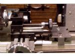
Reproducing the remaining caps to match was the problem (photo 1). Having made a device some time earlier, to help with turning the convex and concave shapes for a small smokebox door, it seemed that the same device could also be used for the ‘hubcaps’ (photo 2).
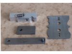
Although specific contours may be possible, the purpose of the device is mainly for repetition work. A block with an anchor point for one end of a spring is first clamped to the lathe bed behind the rear of the saddle.
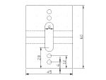
The other end of the spring is attached to a screw on the saddle (the hole for the screw can be drilled using a hand brace), so pulling the saddle towards the tailstock end of the lathe. Mounted on the top surface of the block is a template cut from sheet steel and shaped to a profile (photo 3). By turning the profile around or over, a selection of four profiles can be formed on the same baseplate. Two sets of fixing holes are provided to prevent the centre points of adjoining sections from overlapping.
The ‘Tee’ nut used for securing the top-slide is replaced with a short length of bar, tapped at one end for the top-slide and with a small pin and roller fitted at the other end to act as a cam-follower. With the lead-screw bush loosened, the saddle is drawn towards the tailstock until the roller on the bar of the top-slide ‘nut’ pushes against the template, then by turning the cross-slide feed-screw, the cam will follow the template profile.
Article continues below…
Enjoy more Model Engineer Magazine reading.
Click here to subscribe & save.
A tool ground to a similar shape as that used for thread cutting is set in the top-slide. The top-slide, which is used to feed the tool in, is set parallel with the lathe bed. It is important that should the tool be removed for sharpening, it must be re-positioned exactly, or a change of profile will appear on the workpiece. Only shallow relief is possible and steep angles against the pull of the spring should be avoided, though this is no problem if the angle is with the spring.
A little help will be required at these points when returning the cross-slide for the next cut. Specific template shapes may be possible with experiment, but sharp corners on the template being followed by the roller will appear differently on the workpiece. The tool will also have some effect as the different parts of its cutting edge come into play, during its travel across the work. For keeping the roller of the cam follower in a place, a nail cut to length was used with the hole in the pin drilled to suit.
Article continues below…