We have received payment for the content in this article. Learn more.
Design Points of Sheet Metal Punching
1.For two adjacent holes, the shortest distance from the edge of the hole to the edge of the other hole should preferably not be less than 1.5 times the thickness of the material. Or the female die is easy to crack and the production line is disconnected. Disconnection, mold repair, etc. are the causes that increase the cost and reduce the profit. If it is necessary to be less than 1.5 times the thickness of the material, the tabbing method must be used.
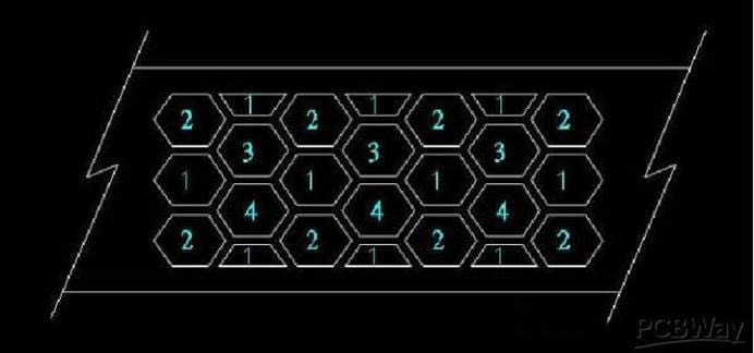
The round hole is the strongest In the mold making, which is easy to manufacture and maintain, but the opening rate is low.
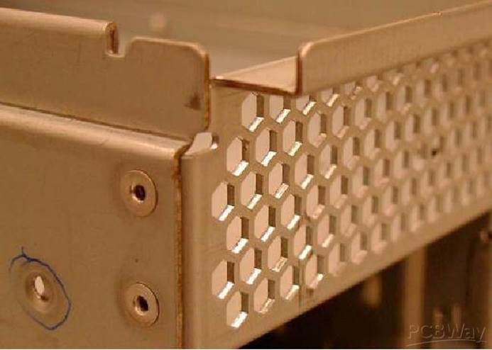
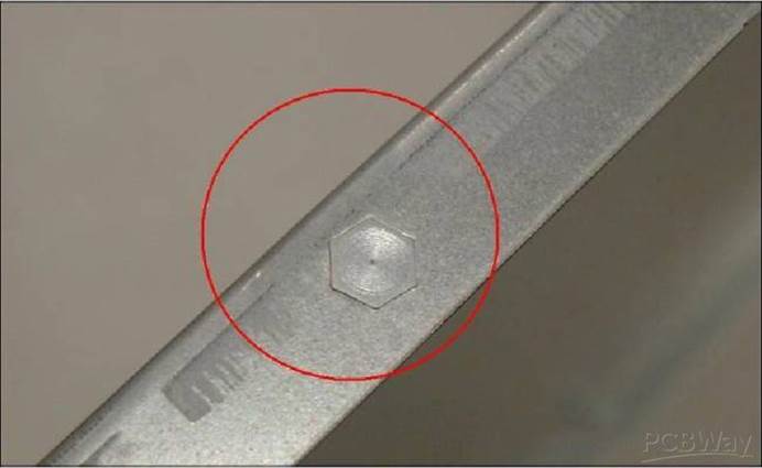
The square hole has the highest opening rate, but the corner edge is easy to wear and collapse because its 90-degree angle, which will result in the need to repair the mold and stop the line. The hexagonal shape has 120-degree angle, which is stronger than the square hole, but the opening rate is a little worse than the square hole at the edge.
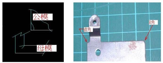
2.When the sheet metal is blanking and punching, there will be R angles and burrs. After the molds in the mass production stage are worn out, the burrs will be more serious and even cut the fingers. Therefore, when drawing the molds, the direction of the burrs must be clearly marked according to the function.
3.When the sheet metal is blanked and punched, the 1/3~2/5 of the cut section close to the male die punch is a flat cutting surface, while the 3/5~2/3 close to the female die is an oblique tear section. When the sheet metal is blanked and punched, the 1/3~2/5 of the cut section close to the male die punch is a flat cutting surface, while the 3/5~2/3 close to the female die is an oblique tear section. Therefore, the size of the aperture is subject to the punch when making the mold or checking the size, and the outer size of the workpiece is subject to the inner size of the female die when blanking.
Design Points of Sheet Metal Bending
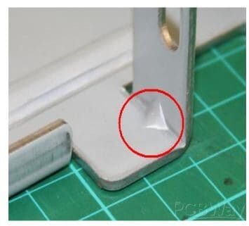
1.After the sheet metal is bent, the metal material will protrude on both sides of the bending angle due to the extrusion material, resulting in a larger width than the original size. The protruding size is related to the thickness of the material used. To avoid this situation, you can make a semicircle on both sides of the bending line in advance. The diameter of the semicircle should preferably be more than 1.5 times the thickness of the material. When the edge material is designed to be folded back, it should be handled in the same way.
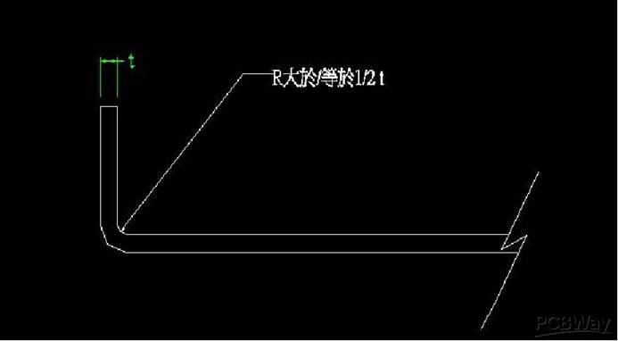
2.When the sheet metal is bent, the internal R angle is preferably greater than or equal to 1/2 of the material thickness. If the R angle is not made, the right angle will gradually disappear after many times of stamping, and the R angle will naturally be formed. After that, the length of one or both sides of the R angle will be slightly longer.
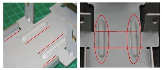
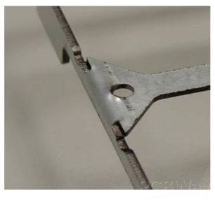
3.It is easy to be deformed by force after the sheet metal is bent. In order to avoid the occurrence of deformation, an appropriate amount of 45-degree reinforcing ribs can be added at the bending position to increase the strength on the principle of not interfering with other parts.
4.Generally speaking, sheet metal parts are not easy to maintain their straightness when they are long and narrow, and are more easily deformed after being stressed. Therefore, we can fold one side into an L shape or fold two sides into a ㄇ shape to maintain its strength and straightness. And an appropriate amount of ribs can be added to increase its strength when the L and ㄇ types cannot be connected from beginning to end and are interrupted by some factors.
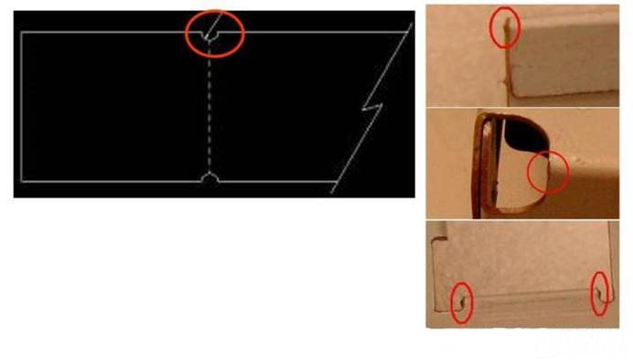
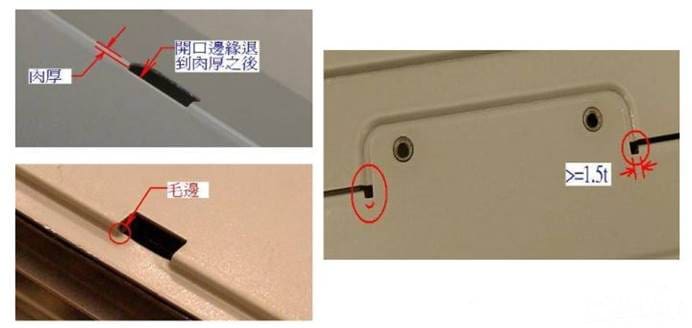
5.The turning point between the plane and the bending surface is best to have a narrow hole, or the edge of the opening should be retreated after the bending, otherwise there will be burrs. Tthe width of the narrow hole is preferably greater than or equal to 1.5 times the thickness of the material. And remember to mark the R angle when drawing. Molds with right or acute angles, male and female molds are prone to cracking. Future line stop and mold repairs are additional losses.
6.Please be sure to handle it as an appropriate R angle at the corner of the edge of the metal sheet if there is no special requirement for a 90-degree angle, because the right angle at the edge of the metal sheet is likely to form sharp points and cut the staff. The right-angled tip of male die is prone to cracks due to stress concentration, and the male die is easy to crack at the tip, which makes the mold must be repaired and delays mass production. Even if it does not crack, it will form an R angle due to wear and tear over time, which will cause the product to have burrs and cause defective products.
7. Folded edge can be divided into single-sided folding and double-sided folding. If there is a requirement for precision, it is best to use double-sided folding for better accuracy. The height of the folded edge should preferably be greater than 3mm. (t: 1.0~1.2mm), otherwise the size will be unstable due to too small clamping size.
7.1When folding the edge, the parts on the side wall or the internal protrusions should not be too close to the bottom surface, preferably more than 10mm. Otherwise, the R angle of the stamping will be larger than the R angle on the left and right sides if there is no male mold at the corner below the protrusion, and the discontinuous R angle will influence the appearance. The solution is to punch out an appropriate length of indentation on the folding line before bending.
7.2When folding the edge, the opening on the side wall should not be too close to the bottom surface, preferably more than 3mm. Or the opening will be deformed due to bending. The solution is to punch out a long hole with the same length as the opening and 1.5 times the width of the material thickness on the folding line before bending, which can cut off the pull without affecting the appearance of the opening.
Design Points of Screw Hole
There are generally three ways to fix the screw:
1.Directly punch or draw holes on the plane of the iron piece. and the use self-tapping screw. For self-tapping screw, triangular self-tapping screw is better, which are less prone to get stripped, and the locking force will be a little heavier than non-triangular self-tapping screws.
If it is screwed with a diameter of 3mm, the hole diameter d should be between 2.4 and 2.5mm.
If it is screwed with a diameter of 4mm, the hole diameter d should be between 3.4 and 3.5mm.
2.Punch through holes or draw holes on the plane of the iron piece, and then tap the threads with screws.
Generally, the mechanical thread of M3 or M4 are attacked.
If it is screwed with a diameter of 3mm, the hole diameter d should be 2.6mm before tapping.
If it is screwed with a diameter of 4mm, the hole diameter d should be 3.6mm before tapping.
If the thickness of the material used is 1.0~1.2mm, it is recommended to use a drawing hole instead of a through hole.
Because when material with the thickness of 1.2mm taps the thread of M3, there is only 2.5 thread, which is easy to get stripped.
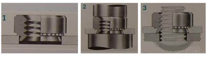
3.Punch holes on the plane of the iron piece, and then rivet the ready-made fixing nut.
The hole diameter d of the riveting set nut is preferably the size recommended by the manufacturer.
It will cost a lot of time and money to process the nuts one by one when riveting the nuts. Therefore, almost all processing plants use general punches for riveting. If the machine used is unfortunately a conventional punching machine, there is a possibility that the nut will fall off, because the punching speed of the conventional punching machine is too fast, and the material of the workpiece will end before filling the nut or stand-off groove. The problem is completely undetectable from the appearance, but some nuts will fall off when the finished product is assembled. Therefore, for the machine used for riveting the fixed nut, it is best to choose a machine that can adjust the stamping speed.
Design Points of Chassis Sheet Metal
In the assembly design of chassis, there are often a combination of 2 pieces, or a combination of more than 3 or 4 pieces. When spot welding, there must be positioning points, positioning pins or fixtures to ensure the correct position. But generally no more will be added if screws or pull studs are used, because there are already opposite screw holes and pull stud holes. However, in order to facilitate assembly, the hole diameter of the screw hole and the stud hole will be designed to be larger, so the relative position between the parts is also prone to errors.
In this case, it is recommended to use the positioning bumps with a small gap for positioning. When doing the T/A Loop operation, it is more accurate to use the positioning points with a small tolerance to do the benchmark calculation.
Before the chassis is opened, it is better to design the position and size of the required mark. Mark it on the instance can facilitate alignment when sticking the mark. There are two most common marks:
1.Make an “L”-shaped mark around the mark, or on the upper and lower sides of the left side, or the left and right sides of the upper side. This method is cheaper to mold, but the mark protrudes from the surface of the instance and is easily scratched.
Before the casing is opened, it is best to design the position and size of the required mark, and mark it on the instance to facilitate alignment when sticking the mark. There are two most common marks.
1. Make an “L”-shaped mark around the mark, or on the upper and lower sides of the left side, or the left and right sides of the upper side. This method is cheaper to mold, but the mark protrudes from the surface of the instance and is easily scratched.
2. Increase the size of the mark by 0.3mm, and make a dent of 0.2~0.3mm at the place to be marked.
No matter what method is used, you can choose an appropriate angle of the four to make a 45-degree lead angle, and make the same 45-degree lead corner at the opposite position of the mark on the example. To be fool-proof, which is used to avoid marking different directions at different times or different staff posted.

Don’t forget to design a large R angle to avoid the occurrence of acute angles where there is a break, or when the upper cover is under heavy pressure, the acute angle will stand against the upper cover and cause a sharp bulge.
In addition to increasing the strength of the chassis, fixing the fan and the air duct, the middle wall can effectively prevent EMI if it is in perfect contact with the inside of the upper cover, which will greatly prevent the noise of the motherboard from emitting from the front, so it is better to avoid placing plastic parts on the middle wall to prevent contact with the upper cover.
How can you order Sheet Metal services?
PCBWay makes most of the industrial-grade prototyping services accessible for everyone. They have great experience in PCB manufacturing and prototyping, and they constantly upgrade their machines to be in front of quality and speed. They have a very convenient website to upload your design and order preferred service with only a few mouse clicks. For instance, if you need a Sheet Metal service, all you need to do is go to the quote form, select necessary parameters, and upload cad files.