Background
Some years ago, a work colleague acquired a fire damaged ‘Startrite’ drilling machine from his local garage, which he found to be oversize for his intended use. I was fortunate in that he agreed to swap it for my smaller budget imported drill, leaving me with the task of replacing smoke damaged label plates and melted plastic ball handles.
I have found my new acquisition to be ideally suited to my use. It is equipped with a No.2 Morse taper spindle and an epicyclic gearbox, giving a range of 10 speeds from 95 to 3830 RPM. The gearbox provides an instant speed change from drilling speed to a reduced speed for countersinking etc. Also in the neutral position, the spindle is completely free to rotate allowing tapping to be carried out in situ without disturbing the work.
I have since made some minor alterations and additions to the machine and found a different way to secure the vice to the table.
Table Support
Once the height has been set and found satisfactory, there is not really a need to move the head again.
Enjoy more Model Engineer reading in the monthly magazine.
Click here to subscribe & save.
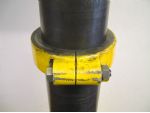
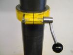
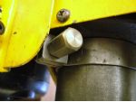
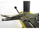
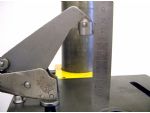
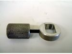
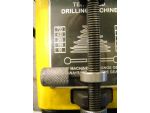
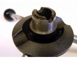
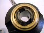
All the parts were removed from the pillar and the split collar replaced first. The nut on the pinch bolt was replaced with a handle operated nut to allow instant release of the collar, photo 2. The table was replaced and a new head safety stop made from strip material secured with an extended nut to give better access, photo 3.
Vice Clamping Bar
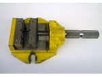
The jaws are 83mm wide opening to 40mm with ‘V’ grooves everywhere. There are hardened step jaws with a capacity of 47mm. Although the ‘Vs’ allow round work to be held securely and provide drill clearance with narrow pieces, the hardened top jaws can mark the work if packing is not used.
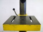
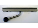
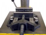
A piece of 3/4in. x 3/8in. flat bar was cut off to span the table slots by 19mm each side, and drilled 10mm for the vice securing bolts and tapped M10 in the centre for the clamping handle.
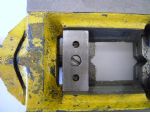
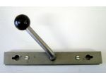
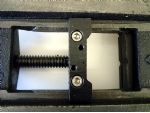
A piece of 3/4in. x 2/16in. flat was cut off to the same length and clamped to the thicker piece to drill through M4 tapping size at 30mm from each end and to spot through the outer fixing holes . This bar acts as a stop piece for the clamping screw, it’s necessary due to the central hole in the table. The thinner piece is tapped M4 and the 10mm clearance holes drilled. The other piece is drilled M4 clearance and counterbored for two pan head screws to keep the pieces aligned with a gap of about 3mm photo 7.
Although not my first choice for a handle, it was made as in the photo to be in keeping with the factory fitted items. A piece of 10mm dia. rod is threaded for about 25mm at one end and the piece screwed into the clamp to lock the vice to the table. The bend location is marked so that the handle will point to the front in the locked position, giving an arc of movement in front of the table when in use. After the bend was put on at about 70deg., a plastic ball knob was fitted onto the end, again as used for the other handles, photo 8.
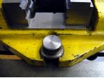
When first made, the clamp was tapped M10 for hex. bolts to secure the vice, but as there is a need to remove the vice to clamp work directly onto the table, or use a different vice, swarf collected in the threads made bolt replacement difficult, as they are only tightened by hand to take up clearance, the locking being done with the handle.
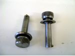
Two knurled peg bolts were made as replacements, photo 9 and two slots and stop pins provided in the clamp bar so the new bolts could be inserted and given half a turn clockwise to lock them in place and the handle used as previously. The tops of the knurled knobs were marked on the pin side to allow easy engagement with the retaining slot, photo 10. The fitted view is shown in photo 11.
No specific measurements are given due to the variation of tables and vices likely to be used, but the pictures should illustrate the requirements. However, when deciding on the free space between the clamping bars and the placing of the peg in the vice bolts, there should be enough movement to accommodate the variations in the thickness of the clamping flanges of the vices intended to be used.
More Capacity
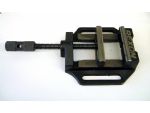
On a visit to B&Q I saw a budget vice on offer for £6, which appeared to be a bit ‘cheap’, photo 12. On examination, it was quite well made, with the same jacking screw arrangement to allow fine setting of the jaw movement, photo 13. The vice was branded ‘Rexon’ with a jaw width of 98mm, opening to 90mm with 98mm available in the jaw steps, so the vice was purchased.
The slots in the base were slightly wider spaced than those in the drill table, but with the bolts being 10mm dia. and both vice and table slots being about 12mm wide, the clamping system could still be used, photo 14. The only work needed on the vice was to clamp it to the table of the mill with the jaws fully tightened, and run a 6mm end mill along the stepped area to even up the bottoms of the steps.
Recycling
Depth Stop
Depth Indication
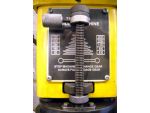
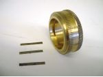
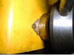
The odd choice of material is due to the only piece available at the right diameter was an old three step round belt pulley in the scrap box. The maximum travel was measured and found to be 90mm with the stop removed, so a 90 tooth change wheel was used to graduate the collar. A small shaped plate was attached next to the collar with a screw to carry the fiducial line, photo 23. One complete revolution is 90 mm travel but only 80 divisions were engraved on the dial, as the dial travel is limited to 80mm. That left a gap of 10 divisions, which can be seen in photo 23.
Drilling Safely
Because the vice clamp bar arrangement is so easily and instantly locked after the vice has been slid into the appropriate position, then ALL drilling operations are carried out with the work held in a vice and with the vice locked down on the table.
Although what has been described relates to a Startrite drilling machine, any machine without the benefit of a rack rise and fall to the table, will be made easier to use with a collar fitted under the table, allowing it to rotate about the pillar without the fear of it suddenly dropping, or the risk of hitting the drill bit when lifting it together with the weight of the vice and the work-piece.
The vice locking system will apply to any through slotted drill table with the exception of tables which rotate around a boss on the attachment arm. However in the case of rotating tables, the clamp bar could be split and the pieces joined with a U shaped bracket, with a larger bearing piece for the locking handle which would bear on the base of the central boss. If the vice used had slotted clamping flanges, then the lock screw bearing piece would not need to move very far from the central position on the boss.


