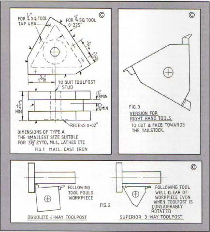
Before you start to say ‘Oh no not another gimmicky toolpost' let me state that this design has now been in use by me for a long time and by friends or other model engineers in this country and abroad for almost ten years. l have yet to hear of anyone who has tried the system wanting to go back to the awkward old fashioned 4 way toolpost with all its drawbacks. In fact one user in Australia was kind enough to write in Model Engineer magazine that the designer of the 3-way toolpost should have been awarded a knighthood for the greatest advance in lathe design for many years. Perhaps he should have written to some other department because I never did get that knighthood. At a display a few years ago the toolposts were shown together with a notice saying ‘Better than a 4·way, quicker than a quick change’. Perhaps at this stage the advantages should be briefly explained. It is well known that the biggest defect of the 4-way is the fact that the following tool fouls the work under certain conditions of use. This means in effect that separate shaped tools must be used for each type of operation, for example a tool used for plain turning cannot normally also be used for facing cuts, if the toolpost is rotated slightly to bring the turning tool into position for facing the following tool immediately fouls the turned portion, with the 3-way toolpost there is ample clearance even when it is rotated through quite a large angle.


- The Lammas Three Way toolpost loaded with raked tools for cutting steel and aluminium.
- Another similar toolpost loaded with zero-rake tools for cast iron and brass. Note one holder is loaded for carrying triangular tungsten carbide tips.
- This version is loaded with asset of tools for right hand cutting.
It will therefore be appreciated that although holding one less tool it can perform more operations, in addition anyone who has caught their hand on a sharp cutting edge with the 4-way type will be pleased to know that with the new system there are only two cutting edges to watch out for instead of three. Taking the other point regarding speed of use; it is readily seen that a toolpost holding 3 tools can be changed over more quickly than the complete removal and replacement of the single quick change type. There is another important aspect to consider here as well, how many individual quick-change holders do you need to buy to get best use from the System? They are not cheap.
Enjoy more Model Engineer reading in the monthly magazine.
Click here to subscribe & save.
Summarising the advantages of my method we can say:
1) Less danger of accidental injury.
2) Fewer shapes of tool do more work.
3) Fouling of workpiece dues not occur.
4) Fast interchange of tools.
5) Cheap to use because the simple casting can be machined entirely on the lathe with which it will be used.
6) Because it is cheap we can afford more than one toolpost. Thus the first is loaded with raked tools for cutting steel or aluminium, the second is loaded with zero-rake tools for brass or cast iron.
7) By the same token, one toolpost can be machined 'upside down', meaning that it will then hold tools for cutting towards the tailstock.
8) Need another for tipped tools? No problem, just order another casting.
By now l reckon even the most sceptical reader should be admitting there may be something to it after all. If still doubtful just ask someone who has used it for in while, it is a fairly safe that they wouldn't go back to the bad old ways.
In the first place the idea was developed for my own use but after it had been seen by fellow model engineers requests to ‘make me one’ came thick and fast. Mine was designed for an ancient 3 ½ inch Winfield lathe which is of similar size to the Myford ML4 and the Zyto. Soon I had to design a larger version to fit the Myford ML7 and similar lathes, The casting supplier now stocks three sizes A .B and C. A is the original. B fits ML7 and C is the largest for the Boxford lathe or similar machines.

- Facing the casting in the chuck, using a HSS tool set in a previously made three way toolpost
Construction
The casting as received is fully shaped but needs machining on all surfaces as indicated on the GA. drawing. The overall size is not critical, just taking of sufficient to clean up is usually enough.
Facing
Grip the casting firmly in the 4-jaw chuck, top outwards with the base resting against the face of the chuck. Take a roughing cut to remove the skin from the cast iron then take at least one more cut of around ten thou (0.010 inch) to achieve a good finish.
Reverse in the chuck pressing the newly machined face hard against the chuck body and repeat the treatment, this leaves top and base flat as well as parallel to each other.
Marking out the central hole
The diagram for this operation shows where to scribe the lines with respect to the finished dimensions of the toolholder. All drawings refer to type A toolholder only, as detailed drawings are supplied with the castings. When scribing the three lines allow for the fact that at least 1/8 inch will have to be added to the 1 3/16 inch dimension.
In any case it is quite easy to see if the lines cross at the centre of the casting. Don’t just rely on two line crossing or errors can easily arise, lust like navigating a boat in choppy waters when compass bearings apt to be slightly out.
Having found the centre, ‘pop’ it with the centre punch then drill it through to suit the toolpost stud of you lathe, making it a close though free fit. The recess round the hole at the base is to ensure that swarf does not get trapped close to the stud. The recess does not have to be accurately concentric with the hole so just set it up in the chuck ‘near enough’, remove about 20 thou (0.002 inch) or so to a diameter of roughly 1 inch.
Machining the sides flat
This can be done, either by flycutting or end milling. Place the casting on the topslide using the toolpost stud to clump it down. It is a good idea to first of all turn and bore the special clamping collar, (Spacer, fig. 5) to be used with the toolpost. Like recessing the base its shape makes certain that a firm grip over a good area can be guaranteed, you do not want the toolpost shifting during machining any more than when it is in use for its legitimate purpose.
The endmill or flycutter can be held in the lathe chuck. If it only cuts over a smallish diameter, say ½ inch, it will be necessary to take several cuts with different sizes of packing.
Turn upside down to complete the coverage. A larger diameter flycutter can do the job in one pass. The various sides of the casting are readily aligned parallel to the face of the chuck by placing a rule across the jaws then moving the saddle until one face of the casting traps the rule.

Milling the tool slots
When all the sides are machined flat bring one side up against the tailstock centre to scribe a short lie along it indicating lathe centre height. Now decide what size of lathe tool you intend using- Years ago I bought ½ inch square tools which were reasonably cheap at the time, but as prices increased I changed over to ¼ inch square tools, which are perfectly adequate for model engineering purposes. There is four times as much steel in a ½ inch tool as in a ¼ inch one and the only advantage with the larger one is that it conducts heat away from the cutting edge more quickly. This might be a factor to consider in industrial work aiming for maximum rates of metal removal but is irrelevant for most of our jobs. So far as rigidity is concerned ¼ inch size has always proved to be satisfactory.
Whether deciding on ¼, 3/16 or 3/8 inch square the rule is that the top of the tool should be at centre height. As the cutting edge is ground lower in successive re-sharpenings the tool is raised a corresponding amount by thin packing strips below it. At least 1/8 inch should be allowed above centre height to accommodate this movement.
Therefore another line must be scribed on the side of the toolpost blank 1/8 inch or so above the line already made, then a third line is scribed below centre height equal to the thickness of the tool. It is only necessary to do this on one side since all three slots will be milled one after the other at the same setting.
If a slot drill or end mill the same size as the slot is available just place packing beneath the toolpost sufficient to raise it so that the end mill coincides with the slot position. Set the casting parallel to the face of the chuck and tighten down firmly. Since large forces are generated when milling do not attempt to cut the slot in one pass but take a series of shallow cuts around 40 thou (0.040 inch) at a time, this will minimise the risk of movement by the toolpost. The total depth of cut should be about 25 thou (0.025 inch) less than the width of the lathe tools to be used. It is a mistake to have the slots too wide.
Where an endmill smaller than the slot is being used it will be necessary to pack the toolpost up in stages. Take the metal out with a series of cuts as described above, then place more packing below and take a second series of cuts. Retain the packing pieces so that the other slots can be dealt with in the same manner.
Completion of a set of toolposts intended for turning steel, brass etc. as well as one for right hand cutting, is facilitated if they are all dealt with as a batch. For instance, face the top and bottom of all the castings before proceeding to flycut the sides. Flycut them all before milling the slots. Do not forget to turn the ‘right hand’ one upside-down before marking out and milling the slots.
Tool Clamping Screws
The old 4-way toolpost was often fitted with square-headed screws which are rather clumsy looking, some modern toolposts are fitted with socket grub-screws thought by some to look quite neat as they sit flush with the top of the toolpost. Think again about these because they invariably fill up with fine swarf that is not easy to remove, their designer should have foreseen that fault. The best method is to use socket cap-screws which being clear of the surface are far less likely to accumulate swarf. Get some that are not too long though. If using 1/4" inch square tools in slots milled for that size only it will be best to employ 4BA cap screws. If 2BA were used the holes would be too close to the edge. 2BA is the ideal size for larger slots.
Only two screws per slot are drawn, which is only enough for new or only slightly worn tools. If you want to use short ends of HSS another hole must be drilled and tapped between the existing ones.
Indexing stop
I have not drawn this item partly because I do not use one but also because readers wishing to replace their old 4-way toolpost will already have part of the mechanism attached to the topslide. It might then be possible to adapt this to the new 3-way posts or at least to make similar new parts that will fit in.
As mentioned earlier one of the big advantages of the 3-way system is that the toolpost can be used at various angles to the topslide giving greatly improved versatility. It does not always have to be at right angles to the slide. The conventional indexing stop mechanism would probably interfere with this feature. An adjustable stop designed to catch one corner of the toolpost can be fitted to the top of the topslide if ability to return to a pre-set position is deemed essential for certain operations, such as making a large number of small screws for instance.

- Flycutting the faces of the casting, which is mounted on the topslide
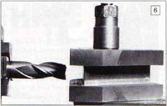
- Cutting the tool slots. This is carried out using an end mill in the chuck. The casting is raised on suitable packing.
The tools
Careful selection of a few basic tool shapes will enable one to perform the majority of turning operations without too may tool changes.
A knife tool, round nosed tool and recessing or small parting off tool will handle most jobs. I like to use a more substantial parting tool in a rear toolpost in any case, so perhaps the small one could be replaced by a roughing tool. Loading the steel, brass and right-hand toolposts with a similar selection will go a long way towards speeding up ones lathework, leaving more time to concentrate on the interesting parts of the task instead of constantly hunting for odd tools of assorted rake angles then wasting time setting them up.
There is no reason why another toolpost could not be kept loaded with boring tools or maybe a boring tool, an internal recessing too and an internal screwcutting tool. Likewise and external vee screwcutting tool, a square thread tool and a chamfering tool already to hand would be very useful there is plenty of scope in this system.
Storage of toolposts on a rack consisting of short lengths of 3/8 inch diameter steel set in a wooden block adjacent to the lathe also helps to speed things up, the tool for the job can be selected without having to think about it and changed instantly. How often have you attempted to do a job with the wrong shaped tool just because it happened to be fitted to be fitted in the 4-way turret and it seemed too much trouble to change it?
When you manage to get away with bodging things in this manner it may seem alright. When the job goes wrong and you have to start again from scratch with the other tool, you begin to wish things were better organised. I believe my toolposts will meet this requirement in an entirely satisfactory manner.
Castings supplier
Castings for the A, B and C toolposts are still available from Blackgates Engineering, Unit 1, Victory Court, Flagship Square, Shaw Cross Business Park, Dewsbury, WF12 7TH. T. 01924 466000. www.blackgates.co.uk
This article first appeared in Model Engineers' Workshop January/February 1995

Events
January 17 – the Great Hanshin Earthquake devastates Kobe, in Japan.
February 9 – Michael Foale becomes the first Briton to walk in space.


