Last month, we levelled up the lathe and checked it for truth. I have had an email about this article asking what to do if the lathe turns out of true. The three Myford lathes I have set up have always been true when set up as suggested but in case your lathe needs adjusting, I will detail how to do it.
Firstly, set up the lathe as suggested last month. If the lathe wont turn true it is probably because the bed is twisted so we need to twist it back to correct it by adjusting the raising block nuts at the tailstock end. If the test piece is larger at the tailstock end, you will need to higher the adjusting nut at the front position. If the test piece is larger at the headstock end, you will need to higher the nut at the rear position. I have not had reason to adjust this so instructions are taken from the Myford Series 7 Manual available from www.myhobbystore.com. You will also need to realign the tailstock after aligning the bed.
Myford series 7 bed stop
Enjoy more Model Engineer Magazine reading.
Click here to subscribe & save.
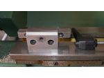
First up this month, I am giving details of a bed stop for the Myford 7 series lathe. This bolts onto the front of the lathe using the gearbox mounting screw holes. The rod is clamped by the locking handle at one end and acts as a dead stop on the carriage at the other end. The construction of the two main components is quite straightforward and nothing is particularly critical although you should try to get the two mounting holes reasonably accurate. The counterbores should be sized to suit the screws used. I would recommend using Allen cap screws.


The two holes that mount the gearbox are usually 1/4in.BSF so I spent a few hours tidying up the storage shed and found the bag of screws, great, I can put the stop back on the lathe (it was removed to avoid damage in transit). Unfortunately, my Myford is quite a new model and Myford in their wisdom had changed the mounting screws to M6. Rather than spend any more hours in the shed, I drove to the nearest DIY store and bought a packet of M6 machine screws which have been used temporarily to bolt the stop on to illustrate this article. I will replace them with M6 when I find the box full.
The support block
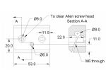
The main block
After reaming the 8mm (5/16in.) hole in the main block, check the location against the lathe to check for clearance. Although the dimensions worked out ok for my ML7R, there have been a number of variations to the size of the lathe back gear handle and you may have to lower the stop slightly so the rod clears the handle. As designed, the support block should be in the middle of the main block. If you need to lower the height of the stop rod, mark out the main block and drill to suit, otherwise drill so the main block is in the centre.

I milled the slot in the vertical mill using a slitting saw but it would be acceptable to use a hacksaw but you use two blades in the hacksaw as this will cut a wider slot. The plastic handle is a standard M6 male threaded handle. The one I used is a large one. If a handle is not available, a bolt could be used instead.
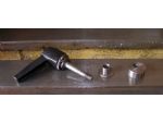
A simple chuck back stop
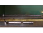
You need a length of 8mm studding and an 8mm nut. The only part you need to make is the top hat adapter. This is turned to fit the mandrel hole leaving a raised portion at the end and drilled through to take the studding. The bar in the collet can be turned to suit the job in hand and the length can be varied to suit the thickness of the work in the chuck.


A carriage lock
 The final item is a replacement carriage lock. This is also simple to make. Again there is a top hat bush. This is turned to fit the hole in the carriage and drilled about 6.2mm for clearance on a 6mm thread. Leave the outside diameter about the same size as the diameter of the plastic locking handle.
The eccentric nut can be copied from the original. From memory it is 11/16in. diameter but check from your example. The quickest way to make it would be to spot through the original nut onto the new one and then drill and tap it M6. The plastic handle is a small M6 one but check that you get one with a long enough thread length. The plastic handle is serrated and spring loaded so you can pull it up, turn it to the position required and drop it back down. This simple accessory means never having to look for the carriage locking spanner in the swarf again.
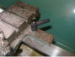
Using the three items
Put a piece of bar into the chuck against the back stop, bring the tool up to the front of the bar and lock the carriage. Using the top slide, put on a cut sufficient to clean up the end of the bar and face the end. Turn the bar round in the chuck and bring the tool almost up to the front of the bar. Bring the stop bar up against the carriage and lock in position. Clean the end of the bar up using the top slide to put the cut on. Remove the bar from the chuck and measure it. Work out how much you need to remove to take the bar to length, put the bar back into the chuck, put the cut on with the top slide and face to length. Assuming you now want to turn say, a 3/8in. long spigot on the end of the bar, turn the topslide handle along .375 and you can then turn the spigot by traversing the carriage backwards and forwards to the stop.
This is a very useful technique for one offs but really comes into its own when you have a lot of identical parts to make. Face them all at one end then reset to face the second end and finally turn all the spigots. Once you have made these three simple items, you will wonder how you ever managed without them. Next month, I will show you how to fit a chuck to a back plate using only the lathe.


