Enjoy more Model Engineer Magazine reading.
Click here to subscribe & save.
Background


The next modification was to provide controlled lateral movement of the table with a feed screw. This was described in Model Engineers’ Workshop Issue 122, photo 5. Although Hemingway Kits do provide such a screw adaptation, I preferred to use a quicker method of positioning the table to either side of the wheel and for the initial setting. As already stated, this method provides 4in. of instant movement and 4in. of controlled movement.

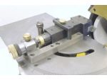
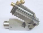
The conclusion was to adopt the feed screw held in a bearing block as in the drill jig. This replaces the threaded block of the original work slide, and also to replace the button in the tool holder with an adapter to hold the nut for the feed screw, photo 8. Although ideally turning the knob clockwise should increase the cut, the thread would have had to be made left handed. In practise, turning the ‘wrong’ way isn’t really a problem as only tiny increments are used during grinding. Is this any different from the subtractive cuts put on when boring in the lathe; which we all do without any problem ?

The slitting saw jig, Figs. 1 to 7 used a piece of 1in. x 1/4in. flat stock to provide the tenon guide in the Work Slide. It was found on completion that with the work table horizontal and a saw blade fitted, the teeth were a significant distance below the centreline of the grinding wheel.

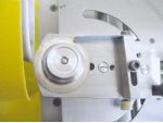
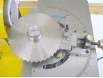


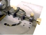
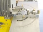
Reducing the height of the clamp screw bracket and moving the V block back level with its support plate resolved this, photo 15. Although reducing the effective length of the drill clamping arrangement, this has not detracted from its use with large drills. I did however find the indexing collars a bit tedious as when rotating the drill for the next lip, any slight movement of the collar caused one of the screws to loosen and the length setting was lost. The insertion of a small steel ball between the lock screw and the V pad with some firm tightening cured this tendency.

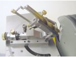
Although the jig is effective for the intended purpose, it is limited to a single angle and will not cope with short drills or centre drills. While wondering what to do with the triangular off-cut from the drill jig body, I came up with a jig adjustable to any angle from 0 to 90deg., photo 16, that will hold and index anything from a centre drill, photo 17 to a 1/2in. drill, photo 18, Figs 8 to 20.

Following the advice of ‘Blind Pugh’ in his excellent articles on Tool-Room Topics, I have since produced a set of both countersink and flat bottom drills with this jig for use with the Allen screws I commonly use, photo 19.
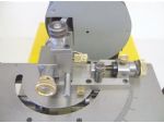
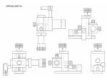
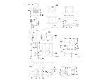
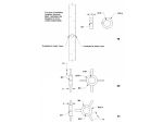
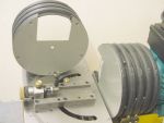
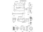
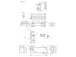
It was felt that there was a need for some form of controlled height adjustment to ease some grinding operations, and a vertical slide type of attachment was made, which was also quickly interchangeable, photo 20, Figs 21 to 41 and vertical slide GA.


|
|
Vertical slide parts list |
|
|
Fig 21 |
Base slide |
BMS – 1in. x 1/4in |
|
Fig 22 |
Feed screw bearing block |
BMS – 1in. x 3/4in |
|
Fig 23 |
Slide base |
BMS – 1 1/2in. x 3/4in |
|
Fig 24 |
Feedscrew bearing plate |
BMS – 1 1/2in. x 1/4in |
|
Fig 25 |
Feed screw |
FCMS – 1/4in. diameter |
|
Fig 26 |
Feed knob |
Brass – 1in. diameter |
|
Fig 27 |
Slide block |
BMS – 1 1/2in. x 1 1/4in |
|
Fig 28 |
Spindle |
PGMS – 5/8in. diameter |
|
Fig 29 |
Spindle knob |
Brass 1in. diameter |
|
Fig 30 |
Slide lock screw |
Brass 1/2in. diameter |
|
Fig 31 |
Tooth rest lock screw |
Brass 1/2in. diameter |
|
Fig 32 |
Spindle lock screw |
Brass 1/2in. diameter |
|
Fig 33 |
Cam plate lock screw |
Brass 1/2in. diameter |
|
Fig 34 |
Cam plate |
BMS 1in. x 1/8in. |
|
Fig 35 |
Tooth rest block |
BMS – 1/2in. square |
|
Fig 36 |
Tooth rest block spindle |
FCMS – 5/16in. diameter |
|
Fig 37 |
Tooth rest spindle |
FCMS – 5/16in. diameter |
|
Fig 38 |
Tooth rest |
Hacksaw blade |
|
Fig 39 |
Index ring |
FCMS – 1in. diameter |
|
Fig 40 |
Cam follower |
FCMS – 1in. diameter |
|
Fig 41 |
Cam follower |
FCMS – 1in. diameter |
Second Lathe Tool Holder

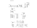
When making or sharpening the ends of lathe tools I found that when the Work Slide was set at 90deg. to the wheel, there was no means of applying a controlled in-feed to the tool bit. This has been resolved with a new Tool Holder with the slot extending along both sides to allow the cut to be applied with the feed screw, photo 24.

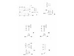
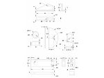
The radius at the point of contact with tool to wheel remains constant and further cut is applied with the screw bearing on the rear of the tool, until the amount of radius required is formed on the end of the tool. This sounds fiddly, but in practice accurate radii can be imparted onto form tools very quickly. Figs 42 to 53 and radius table GA.
|
|
Radius table parts list |
|
|
Fig 42 |
Slide Base |
BMS – 1in. x 1/4in. |
|
Fig 43 |
Feed screw bearing |
BMS -1in. x 3/4in. |
|
Fig 44 |
Table pillar |
FCMS – 1in. diameter |
|
Fig 45 |
Table |
3mm Sheet – 3in. x 1 1/2in. |
|
Fig 46 |
Table guide |
BMS – 1 1/2in. x 3/4in, |
|
Fig 47 |
Tool holder |
BMS – angle 1in. x 1/8in. |
|
Fig 48 |
Tool clamp |
BMS – 1/2in. x 1/4in. |
|
Fig 49 |
Feed nut |
FCMS – 1/2in. diameter |
|
Fig 50 |
Clamp screw |
FCMS – 3/8in. diameter |
|
Fig 51 |
Feed screw |
FCMS – 3/8in. diameter |
|
Fig 52 |
Tool holder clamp |
FCMS – 1/2in. diameter |
|
Fig 53 |
Clamp handle |
FCMS – 1/8in. diameter |
Slitting Saw Grinding Attachment HK 1306
The above items are available from Hemingway kits.


