One of the main uses of CNC machines is the production of complex profiles. Profiles can often be programmed and milled faster than you can set up a rotary table. Once you have had a little bit of practice at programming, even one offs become quick and easy. In the Practical Engineer article on page 15 Issue 147 I mentioned that I had decided to make the George Thomas Pillar Tool and Mini Drill. The component machined for this article is the operating lever handle for the Mini Drill.
When using a CNC mill, you should have a think about how to hold the raw material. Yes, you can cut it to finished size plus a small cleaning up allowance but then you may find the component is difficult to hold. A little bit of forethought will enable you to make complicated components with ease.
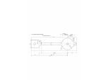
The component shown in Fig. 1 is just such a case. Everything to the left of the 80.5 dimension is not required on the finished component. The 24mm wide bit with the hole through is purely to hold the component down. I drilled the two holes 6mm diameter and used 6mm bolts to bolt the component down to a bit of mild steel held in the vice.
I moved the mill in the X and Y directions so that the main hole at the left is in approximately the centre of the bar in the vice and 27mm from the right hand end of the bar. I zeroed the mill X and Y axes and using a simple program, drilled two 5mm holes in the bar.
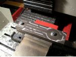
Then I took the bar out of the vice and drilled 6mm through both holes in the drilling machine. I put another bit of bar into the vice and ran the drilling program again to drill the holes in the fixture. I then tapped these 6mm to hold the blank material down, photo 1.
Enjoy more Model Engineer Magazine reading.
Click here to subscribe & save.
To do CNC programming where you have to do co-ordinates, it is much easier to use a cad program to do the required drawing. I did the CAD drawing, Fig. 1 with TurboCAD working from George Thomas drawings purchased from
www.myhobbystore.com. I converted the imperial original to metric for ease of programming. Nothing was critical so I rounded to the nearest whole dimension except for the intersection points of the various radii. I set the CAD package to three decimal places, this being near enough for the machine not to throw a wobbly. The biggest deviation in size was the long thin arm; this was originally 1/4in. (6.35mm). I changed this to 7mm for ease of programming.As we are using internal as well as external radii, we have to decide on the maximum size of cutter we can use. Obviously, if we use a cutter with a radius larger than one of the internal radii on the component, the machine will stop and throw up an error message. The original radii were 1/4in. (6.35mm) and I chose to use 6.5mm for my drawing. I also chose a cutter of 10mm diameter but as shall be seen, this does not necessarily mean that we have a working radius of 5mm (1/2 the cutter diameter). By using the G code G41 we can make the cutter offset to the left, see MEW issue 142, page 37.
Normally we use the correct size cutter to give the correct offset. For the 10mm diameter cutter we are using we would put an offset into the tool offset table of 10mm. This would mean that using the G41 command, the cutter would offset to the left by 5mm. However, we want to rough out the component first so if we use a cutter offset diameter of 11mm, the cutter would move out 5.5mm and leave 0.5mm on the outside of the profile for finish milling later. As long as our minimum internal radii are larger than 5.5mm we will be ok. Where possible, it is best to put on the G41 command in fresh air. The chain dotted line in Fig. 1 is the outline of the billet.
First, we move to the start point, which is X-120.0 Y20.0 at the left hand end of the job. After moving down in the Z direction we move to X-120.0 Y12.0 using G41 to give us our 5.5mm offset and G1 feed movement with a feed of 100. Then we move along the billet to X-87.0 Y12.0 followed by X -87.0 Y10.0, which takes us to the start of the first radius. As this radius goes in the Counter Clockwise direction, we use the G3 command. A simple method to remember if you need to use G2 or G3 is G3 = Counter Clock Wise (three words) or G2 = Clock Wise (two words).
First, we move to the start point, which is X-120.0 Y20.0 at the left hand end of the job. After moving down in the Z direction we move to X-120.0 Y12.0 using G41 to give us our 5.5mm offset and G1 feed movement with a feed of 100. Then we move along the billet to X-87.0 Y12.0 followed by X -87.0 Y10.0, which takes us to the start of the first radius. As this radius goes in the Counter Clockwise direction, we use the G3 command. A simple method to remember if you need to use G2 or G3 is G3 = Counter Clock Wise (three words) or G2 = Clock Wise (two words).
The line reads
G3X-80.5Y3.5R6.5
This means move to X-80.5 Y3.5 in a Counter Clockwise direction on a radius of 6.5mm. Then we move to X-21.817 Y3.5 in a straight line. Then we do another G3 move to X-15.909 Y7.292 with a radius of R6.5. Now we change direction and do a G2 move to X15.36 Y8.385 with a radius of R17.5mm. If you look at the drawing, Fig. 1, it may look as though some of the dimensions are not included but the drawing is symmetrical from top to bottom so all the dimensions are there. (Actually, I missed the dimension of the end flat off the drawing so I guessed this at 24mm to the end flat. This dimension is totally unimportant and the end will be skimmed across the face anyway.)
The rest of the profile is done in the same way. When we come to take the compensation off with the G40 command, I prefer to raise the cutter above the job and any clamps as it is not always obvious how the machine will take the compensation off. Photo 1 shows the profile machined onto the top of the blank to a depth of about 0.2mm to prove the program.
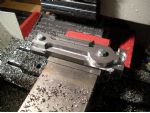
Rather than waste time programming the profile at different depths, as this was only a one off component, I programmed the first Z move to -1.0 mm in the program and changed the depth after each pass by lowering the Z 1mm at a time. Photo 2 shows the component after 8 passes. The waste material can clearly be seen.
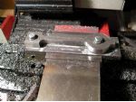
When we cut the final pass, the waste material will drop off the blank, photo 3. Now we have reached the full depth of cut, we can reduce the diameter of the cutter offset and make further passes to take the finished profile down to size. When you have run round at the finished size, I would take a finish pass to take out any spring in the cutter and the job.
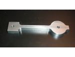
The finished component is shown in photo 4. I will leave the square bit at the end in place until I have done the drilling and slotting of the arm. It will make it easier to set the component up parallel for further operations.
This is the complete program to do the profile. The preparatory moves are the same as used in previous programs. I suggest you work through the program using Fig. 1 and you should then understand how to produce a simple profile. All you really need to do external profiles are the G1, G2 and G3 commands together with the G41 offset command.
G0 G15 G17 G21 G40 G49 G50 G69 G80 G90
G91 G28 Z0. X0. Y0.
M6 T1 S2000
G54 G90 G0 X-120. Y20. Z75.
G00 G43 H1 Z50.0 M3
G0Z5.
G1Z-1.0F100
G1G41X-120.Y12.F100
X-87.Y12.
X-87.Y10.
G3X-80.5Y3.5R6.5
G1X-21.817Y3.5
G3X-15.909Y7.292R6.5
G2X15.36Y8.385R17.5
G3X21.065Y5.R6.5
G1X24.Y5.
X24.Y-5.
X21.065Y-5.
G3X15.36Y-8.385R6.5
G2X-15.909Y-7.292R17.5
G3X-21.817Y-3.5R6.5
G1X-80.5Y-3.5
G3X-87.Y-10.R6.5
G1X-87.Y-12.
X-120.Y-12.
G0Z10.
G0G40Y20.
G0 G49 Z50.
G91 G28 X0. Y0. Z0. M5
M30
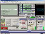
Fig. 2 shows a screen shot of the program in MACH3, the left hand side shows the cutter path.


