This month, we move onto simple profiling starting with the G12 and G13 circle cutting cycle and continue with straight cuts using the G41 offset left command. This is quite a long program as it cuts five holes and then cuts the profile. In future articles, unless very short, I will limit the program to the relevant bits and leave the beginning and end off. Program 1, lines N1 to N5 (with dimensions altered as necessary) will set up the start of your program and lines N55 to N57 will end the program. If you put these lines into a text document, leaving a gap to insert the different codes, you can use this as a basis for all your future programs. Note, you do not need the line numbers. They are optional. I have only put them in for your benefit.
It has been suggested that I explain the reason for the set up and also the cancel G codes in line one. They are there in case you stop a program in the middle. This could leave certain codes still active, which could be dangerous or the program may not work. As we learn the G codes to set an operation, we will also learn the G code that cancels that operation.
N1 G0 G15 G17 G21 G40 G49 G50 G69 G80 G90
N2 G91 G28 Z0. X0. Y0.
N3 M6 T1 S4000
N4 G54 G90 G0 X-16.5 Y0. Z100.
N5 G0 G43 H1 Z50.0 M3
N6 G99 G91 G81 X0. Y0. R1.5 Z-0.2 F30.
N7G90
N8 G80
N9 G1 Z-0.2 F100
N10 G13 I0.5 F10
N11 G0 Z2.5
N12 X-9.
N13 G99 G91 G81 X0. Y0. R1.6 Z-0.2 F30.
N14 G90
N15 G80
N17G1 Z-0.2 F100
N18G13 I0.65 F10
N19G0 Z2.5
N20X0.
N21 G99 G91 G81 X0. Y0. R1.5 Z-0.2 F30.
N22 G90
N23 G80
N24 G1 Z-0.2 F100
N25 G13 I0.5 F10
N26 G0 Z2.5
N27 X9.
N28 G99 G91 G81 X0. Y0. R1.5 Z-0.4 F30.
N29 G90
N30 G80
N31 G1 Z-0.2 F100
N32 G13 I0.65 F10
N33 G0 Z2.5
N34 X16.5
N35 G99 G91 G81 X0. Y0. R1.6 Z-0.4 F30.
N36 G90
N37 G80
N38 G1 Z-0.2 F100
N39 G13 I0.5 D1 F10
N40 G0 Z2.5
N41 G0 G49 Z50.
N42 G91 G28 X0. Y0. Z0. M5
N43 M0
N44 G90 G0 X-30. Y15.
N45 G00 G43 H1 Z50.0 M3
N46 G0 Z3.
N47 G1 Z-0.5 F50
N48 G1 G41 Y12. F80
N49 X26.
N50 Y-12.
N51 X-26.
N52 Y14.
N53 G0 Z10
N54 G40
N55 G0 G49 Z50.
N56 G91 G28 X0. Y0. Z0. M5
N57 M30
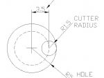
G12 & G13 circle cutting cycle
G12 cuts a circle in the clockwise direction and G13 cuts the circle in a counter clockwise direction. On Mach3, both G12 and G13 ignore radius compensation. This means you have to program the radius of the circle less half the cutter dia. If the circle is too large or too small, you will have to alter the radius of the cycle dimension to get it right.
Enjoy more Model Engineer Magazine reading.
Click here to subscribe & save.
G13 will climb mill, counter clockwise. G12 will conventional mill clockwise. The diameter of the finished hole will be the same (subject to the cutter pushing off) whether you mill clockwise or counter clockwise. Note that the cycle will only cut a circle. If you need to cut a circular pocket, you will have to program two or more G13 (or G12) cycles with overlapping paths.
Cutter compensation G41 and G42
Now we move on to lines N44 to N54. This uses cutter compensation command G41 to run round the outside of the profile of a component. I have used a simple rectangle as an example. Radiused profiles will be discussed next time.

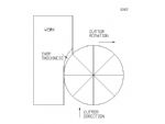
G42 is cutter compensation right, Fig. 3. This means that the cuter is offset to the right in the direction of travel and is conventional or up cut milling. This pushes the job away from the cutter. The chip starts small and gets larger as the tooth digs into the work.
Cancelling compensation, G40
Cutter compensation is cancelled by G40. You need to be careful how you remove compensation as results can some times be unpredictable. If possible, I prefer to raise the cutter at the end of the cut prior to taking compensation off.
N44 G90 G0 X-30. Y15
Line N44 sets absolute (G90) and moves to the start position for the profile. This is outside the profile and far enough away so that the cutter does not encroach on the profile. The X dimension is 4mm to the left of the start of the profile. In practice, it is not a critical dimension, I picked it at random to avoid the profile.
N45 G00 G43 H1 Z50.0 M3
Line N45 sets cutter height and compensation as mentioned last time.
N46 G0 Z3
Line N46 stops the cutter above the material. (It is not advisable to plunge straight into the work even if there is no material in the way.)
N47 G1 Z-0.5 F50
Line N47 lowers the cutter to depth at a controlled feed rate.
N48 G1 G41 Y12. F80
Line N48 moves the cutter in a Y direction to the edge of the job but leaves it offset by the cutter diameter. Note, you must put the correct tool diameter in the tool offset table before running the program. The tool used in this program was 2mm diameter. (You can lie to the program about the tool diameter offset but the reasons for that will the subject of a later article.)
N49 X26
Line N49 moves the cutter to X 26 + tool radius = 26mm + 1mm making 27mm.
N50 Y-12
Line N50 moves the cutter in the Y direction to -12mm + the radius (1mm) making 13mm.
N51 X-26
Line N51 moves the cutter to x-26 + the cutter radius making -27mm.
N52 Y14
Line N52 moves the cutter in the Y direction to Y 14 + the cutter radius making Y 15mm. Again this finishing point is not critical as long as it goes past the edge of the profile.
N53 G0 Z10
Line N53 raises the cutter 10mm above the work.
Line N54 uses G40 to cancel the compensation.
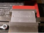
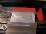
The end holes (ignore the large one as that was already in the material) and the centre one was tapped M3 to hold the plastic down.
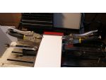
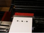
The machine then ran round the profile finishing the part off. In a simple fixture job like this, the centre hole is position X0, Y0. After you have drilled the holes when making the fixture, dont alter your G54 position. When you program the pockets and the profile using the same X 0 Y0, they will be automatically correct.


