This time, lets do something useful to demonstrate the power of a simple CNC program. The first program is the test program used in the review of the KX1 in Trade Counter.
All it does is mill a groove in a bar and then it drills holes along the bar using a simple repeat command. The second program drills 28 radial holes in a disk, again using the repeat function.
Program 1
Enjoy more Model Engineer reading in the monthly magazine.
Click here to subscribe & save.
N2 G91 G28 X0. Y0. Z0.
N3 M6 T1 S1000
N4 G54 G90 G0 X0. Y0. Z50.
N5 G0 G43 H1 Z10. M3
N6 G1 Z-0.5 F500
N7 X-100.0 F50
N8 G0 G49 Z50.
N9 G91 G28 X0. Y0. Z0. M5
N10 M6 T2 S1000
N11 G54 G90 G0 X-50. Y0. Z50.
N12 G00 G43 H2 Z10.0 M3
N13 G98 G91 G83 X0. Y0. R2. Z-19.0 Q4. F10.
N14 X10.0 L4
N15 G80 G0 G49 Z50.0
N16 G91 G28 X0. Y0. Z0. M5
N17 M30
N1 G0 G15 G17 G21 G40 G49 G50 G69 G80 G90
Starting with program1, line N1 step by step. The first thing to do with any CNC program is to start it with the correct commands to set the initial state of the machine. G0 sets the feed rate to rapid. G15 cancels Polar coordinates. G17 sets the X Y plane (for circular moves). G21 sets the control to metric input. G40 cancels cutter radius compensation. G49 cancels tool length offsets. G50 cancels the scaling function (I have never used this in over 25 years but I include it here for completeness). G69 cancels coordinate rotation. G80 cancels any active fixed cycle and finally, G90 sets absolute dimensioning. Dont worry about these G codes yet, we will discuss them as required.
Line N2 starts with G91 to set incremental mode. This is needed to stop the control moving the head and table to the zero point before going to the reference points set by G28. The G28 points are set when the control is switched on and you use the Ref All button. If you set the machine to zero directly onto the job without using the G54 command, you can leave this line out. Make sure that the tool is clear of the work and clamps etc. in Z before running the program. If necessary jog the tool up in Z.
Line N3 selects M6 for the tool change, T1 selects the tool and S1000 selects the speed of the spindle.
Line N4 selects work offset G54, sets absolute dimensioning with G90 and rapid feed with G0. It then moves the tool and table to position X0. Y0. Z50. Where Z is a point above the job that will miss all clamps and vices.
N5 G0 G43 H1 Z10. M3
Line N5 tells the machine to move in rapid G0 to Z10. and G43 says include tool offset H1, (this was set in the tool offset table in part 2) and M3 switches the spindle on.
N6 G1 Z-0.5 F500
Line N6 tells the spindle to feed down in Z to -0.5 using G1 controlled feed at a rate of 500mm per minute.
N7 X-100.0 F50
Line N7 tells the table to move to X-100.0 at a controlled feed of 50mm per minute.
N8 G0 G49 Z50.
Line N8 tells the control to move in rapid (G0) to Z50.0 removing cutter length compensation, G49.
N9 G91 G28 X0. Y0. Z0. M5
Line N9 is the same as line N2 with the addition of M5 to switch the spindle off.
N10 M6 T2 S1000
N11 G54 G90 G0 X-50. Y0. Z50
N11 is the same as N4 but with different coordinates.
N12 G00 G43 H2 Z10.0 M3
N12 is the same as N5 with compensation H2.
N13 G98 G91 G83 X0. Y0. R2.0 Z-19.0 Q4. F10
N13 calls a peck drilling cycle. G98 tells the control to return to the initial starting point after each drilled hole. This would be Z10.0 as set in line N12. G91 sets up an incremental move, G83 is the peck drilling cycle itself. X0. Y0. Is the first hole position. As this cycle has G91 incremental before it, the hole will be in the position programmed in the move prior to calling the cycle. This is line N11, X-50.0 Y0.0. Calling an X0.0 and Y0.0 move in incremental means that the table will not move but the drilling cycle will start as the machine thinks it has made a move. R2.0 tells the drill to rapid to 2mm above the job, Z-19.0 tells the machine the depth to drill to from Z0.0 and Q4. Tells the machine the number of pecks to drill to full depth. Finally, F10. Gives the feed rate in mm per minute.
N14 X10.0 L4
Line N14 will move the table in X by 10.0 to X-40.0 (remember, we are still in incremental) and the L4 will repeat this a further 3 times so we end up with a row of holes spaced 10mm apart finishing on X-10.0.
Line N15 cancels the drilling cycle with G80 and removes the tool length offset while returning to Z50.0
N16 G91 G28 X0. Y0. Z0. M5
Line N16 is the same as N9.
N17 M30
Drilling cycles
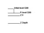
Next, we will take a closer look at the drilling cycle G83 and also at the G82 spot drilling and the G81 drilling cycles. The initial level and the retract level are best shown in a diagram, Fig. 1.
The initial Z level
This is the level that the Z is at prior to calling the drilling cycle. It will be the end position of the previous programmed move.
The R level
The R level is usually known as the retract level. This is a level that can be set above the hole to be drilled where the drill stops feeding in rapid and changes to feed.
G81 is used for shallow drilling and centering were a dwell at the bottom of the hole is not required. It will move to the x y position in rapid mode, it will rapid to the R level, feed to the Z depth and rapid retract to the R level G99 or to the initial level with G98.
G82 spot drilling cycle
G82 is the spot drilling cycle. It is the same as G81 except that the tool will dwell at the bottom of the hole for a time that has been programmed in milliseconds, P100 = 100 milliseconds.
G83 Deep hole drilling cycle
G83 is as G81 with the addition of a pecking cycle so it drills the hole in programmed steps.
Program 2
N1 G0 G15 G17 G21 G40 G49 G50 G69 G80 G90
N2 G91 G28 Z0. X0. Y0.
N3 M6 T1 S5000
N4 G54 G90 G0 X0. Y0. Z100.
N5 G0 G43 H1 Z50.0 M3
N6 G16
N7 G98 G91 G81 X45. Y0. R2. Z-2. F10.
N8 Y15. L23
N9 G80 G0 G49 Z50.
N10 G91 G28 X0. Y0. Z0. M5
N11 M30
Polar coordinates
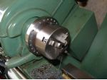
Program 2 will drill a series of 24 holes at a radius of 45mm on the chuck backplate that was fitted in the Practical Engineer article in this issue. The holes are intended to be used with a simple dividing arrangement to be described in a future issue.
The program is very similar to program one until we get to line N6. G16 switches polar coordinates on. Polar coordinates are programmed in angles with the three oclock position as zero degrees (the degrees increase to 360 in an anti clockwise direction). Line N4 moves the table to the centre of the polar coordinates, in this case, X0. Y0.
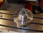
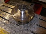
This is then changed to a 4.5mm drill and drilled all the holes, photo 3. The machine was programmed at a reasonable feed rate for drilling but as I was drilling dry, I did not attempt to run the machine too fast or to take deep pecks. The drill was not even warm after drilling all 24 holes.
I then changed the 4.5mm drill for a 5mm one and upped the feed a bit and ran the program again. If you double drill like this, you should get a size hole even if the first drill cuts a bit oversize.