There have been several articles in MEW dealing with the conversion of a manual milling machine to a CNC version. These have all been well written and informative; however, the information that has been omitted is probably as important to the reader as the information published. This is the Now I have converted it to CNC, how do I program it to do something useful? sort of information. This series will rectify this omission.
I know a lot of readers will not be interested in CNC milling but will prefer to stay with manual milling. I would ask you to bear with me as you may find something of interest in this series. Rather than stick completely to programming, there will be useful information on milling in general including setting up a mill, how to locate and machine various components – both simple and complex and will also include details of different cutter types and holders.
Enjoy more Model Engineer Magazine reading.
Click here to subscribe & save.
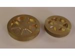
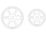
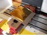
A pair of typical components for CNC manufacture are shown in the photo below. They are brass driving and trailing wheels for 2 off 16mm scale Talyllyn railway locomotives. Eight driving wheels were required, four for each of the two locomotives and two trailing wheels are required for one of the locomotives. This could be done manually on a rotary table but it would take a long time and would be prone to mistakes. The original drawing is shown in the middle and the method of finding the CNC path is shown at the right. All X & Y positions were taken from the original CAD drawing and entered into the CNC program manually. The Z depth is added from the original design information for the wheel and I believe was two different Z depths for the driving wheel and one depth for the trailing wheel. You could use a CAM (computer aided manufacturing) system, which would be quicker once you have learnt how to use it, but I believe you should learn manual G code programming first as you can never be sure if the program written with the CAM will do what you expect. If it does generate an error, you need to know G code to find it.

The basics of milling clocking the vice
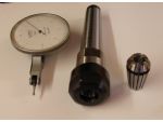
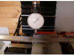
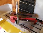
One of the first things to learn is how to clock a vice true. Excluding angled cuts, every time you put a vice onto a machine table, you should use a test indicator to true the vice up. Even if you are only facing a piece of bar on the top where it does not matter if the vice is parallel, you should still clock the vice true. The reason is that the next component you machine may need to be true and if the vice is not true, beforehand, you may well forget to true the vice up with a scrap component as a result. I know, been there, done that.
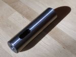
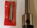
As the clock has a 1/4in. shank, I used an ER collet holder to hold it. To tighten up the holder, I use a plain 1in. shank Morse Taper No2 socket, held across the tang slot to stop it turning, as a tool block held in the vice. When not in use, I cover the socket up with an old holder sleeve to prevent swarf getting in.
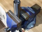

When using two vices, it is important that the vices, where the parallels sit, are at the same height. I measured the vices with a 1 to 2in. micrometer and found a difference between the two of about 1.05mm. The original intention was to use a bit of shim under the low vice but because of the large height difference, I used a piece of 1mm sheet steel and a 0.002in. brass shim, the brass was put under the steel.
Whether manual or CNC, you usually need to find the exact position of two edges of the component to act as a datum. I have always used an edge finder (wobbler) for this. Years ago, I used to use the type with a shank and a ball attachment. For the last ten years or so, I have used the parallel shank wobbler with an inverted top hat component below. I have found them very accurate and they will do most of what I require. I usually run wobblers at about 600 RPM although they usually perform well over quite a large speed range.
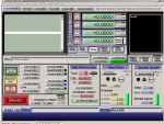
When you switch on the CNC mill and computer, you will need to home the machine first. This involves sending the X, Y & Z axes to the home position using the Mach 3 software. You should set the Mach 3 to automatically zero the axes displays when home position is reached. This datum will remain as long as the machine is switched on and if you switch the machine off and then back on again, after re-homing the readouts should be in the same position. This is the home position.
Because the home position is rarely if ever at the corner of the component to be machined, we need a method of offsetting the program so that the machine knows where it is in relation to the home position. We do this by using offsets. The first offset to use is usually G54. If you jog the machine to the edge of the workpiece and use the wobbler to find the edge, by clicking the correct button on the setting screen, you can set the G54 in the X (or Y) direction. Dont forget to enter the wobbler diameter on the setting screen. (Setting Z will be covered in the next part of the series.)
Not all machines have homing switches. In this case, all you can do is take the machine near to the X, Y & Z limits and set zero there. You will have to set Zero and the G54 each time the machine is switched on. I expect there may be ways around this but having only ever used machines with homing, I cant think of any. If you know, please let us know via Scribe a Line.
Machining coordinates are normally entered into a program as X1.0 Y-10.0 Z25.0 etc., but what does this mean? The fig shows all you need to know for the X & Y axes. The green vertical line is the X 0.0 point and the green horizontal line is the Y0.0 point. All Y dimensions above the green line are positive and all Y dimensions below the green line are negative. All X dimensions to the left of the green line are negative and all X dimensions to the right of the green line are positive. The point where the two green lines cross is X0.0 & Y0.0, this is known as the origin.
G codes straight linear moves
It was my intention to go straight into G code but having digressed, I will do so now. There will be much more programming information in the next issue. I will start with G0 & G1. These are G0, which is a rapid feed movement at maximum travel speed and G1, a movement at a programmed feed rate.
G0 is used for fast positioning moves, for instance to move the X, Y & Z back to the home position after a machining operation. On the other hand, G1 will move directly from +X0.0 and +Y0.0 to +X50.0 & +Y25.0 at a programmed feed rate.
It is the normal convention to omit the + when the position is in the positive direction and to add in the negative direction. The + was used in the first examples for clarity but will not be used from now on. Next time, we will look at how to set the Z datum, the tool heights and tool diameters. We will also look at some more G codes.


