Background
When I ordered the kit for the Versatile Dividing Head, I went the whole hog and also ordered the milling kit and the swivel base; designed by Mr. L. Downs.
As I had mounted the Dividing Head on an adaptor plate to attain the centre height and Tee slot spacing of my lathes cross slide, the revised mounting holes in the body casting would not allow fitting to the Swivel Base without drilling additional mounting holes, which was not desirable. Typically, I had not thought it through before placing the order.
Enjoy more Model Engineer Magazine reading.
Click here to subscribe & save.
Having spent several days looking at this lump of cast iron, (an expensive door stop) I realised that it would provide a swivel base for my Spin Indexer, and moreover; a swivelling base for a machine vice.
Brilliant! But with an overall flange diameter of over 6 inches, the next problem was how to cut the circular Tee slot on a 4 inch rotary table?
Swivel Base Casting Fig.1
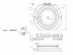
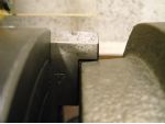
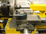
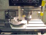
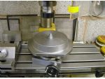
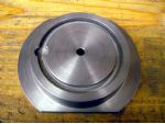
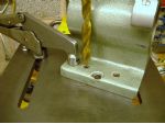
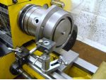
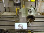
This is a substantial lump of iron to machine and involves some interrupted cutting. The casting was held by the circular boss in the reverse jaws of a 6″ four jaw chuck, but due to the taper of the boss, only the tips of the jaws were in contact, photo 1.
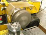
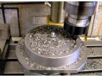
The casting was rotated until even contact was made on the steps of all of the jaws and the cored hole in the base set running true. A pair of twiddling knobs allows horizontal pairs of jaws to be adjusted together; which speeds up the setting process, photo 2.
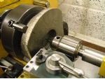
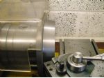
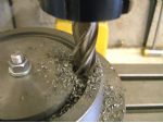
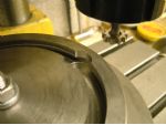
A centre was made in the bottom of the hole to allow additional support to be provided with a rotating centre, photos 3 and 4. This was one of the rare occasions when the topslide required mounting in its alternative position, to allow the outside edge of the casting to be reached.
The base flange was faced to clean up and another cleaning cut taken along the outside edge. With the tailstock withdrawn, the cored hole was opened up with a boring tool to 60mm dia. to a depth 1mm greater than the clearance for the tips of the jaws of the three jaw chuck used to then mount the casting by this bore.
The carbide tool was used to face the top of the boss and clean up the tapered portion and the top of the flange, photo 5. A round nose HSS tool was used to finish turn the taper on the boss at 6º, and provide a radius at its junction with the flange, continuing the cut to finish the top of the flange, photo 6.
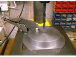
The centre hole was opened up to 6mm as this was the largest drill able to clear the chuck jaws. The casting was clamped to the table of the pillar drill and aligned with the 6mm drill. This was replaced with a 9mm drill followed by 9.5mm, ready to ream to ⅜” dia, photo 7.
This hole was used to mount the casting on the mill table on a card washer to finish the two straight portions of the flange. Although everything seemed secure enough, two clamps were also used as backup, photo 8.
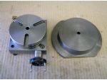
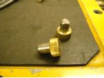
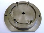
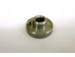
I have a 4″ geared rotary table, which has a ⅜” dia. centre hole used for location and setting purposes. There is an M6 threaded flanged bush fitted in the bottom of the hole used for mounting work on a suitable hollow pin. The size difference is shown in photos 9 and 10.
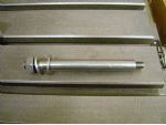
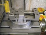
A piece of ⅜” dia. bar was threaded M8 at one end and M6 at the other in order to clamp the work on the rotary table, photo 11. With the rotary table fitted to the mill, the casting was located on the card washer and secured with a nut and washers on the stud, photo12.
An 8mm slot drill was aligned with the top of the stud and the table moved to the left a distance of 45mm. The slot drill was fed in to a depth of 9.5mm and then raised to take a cut of 4mm around the slot, photo 13. This is where it is handy having a workshop vacuum cleaner. After a good suck, a further 4mm cut was taken, followed by a final cut of 1.5mm, the slot being cleaned out after each pass.
With the slot at its starting point, a ⅝” dia. end mill was fed down to a depth of 10mm to provide access for the Tee slot cutter, photo 14.
There then followed a very slow process of cutting the Tee slot with much relief when it was finished, photo 15.
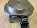
As can be seen, I was a bit too enthusiastic with the end mill. Photos 16 and 17 shows the base machining completed.
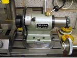
The Spin Indexer
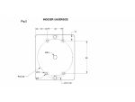
The body of this item is another large and awkward casting to hold. The centre of the base was found and lightly punched. This mark was used to locate a pair of dividers set to 45mm, and light circle scribed at the PCD of the Tee slot, and the four mounting hole positions marked, as per Fig.2 and punched.
The casting was clamped to the drill table on its base to spot-face the mounting holes, which being drilled undersize meant that the pilot was working, thus ensuring the larger diameter did not wander, photo 19. The holes were finally opened up to 5mm diameter for the fixing screws.
To avoid having to make traditional tee nuts, which would need inner and outer radii for clearance in the circular tee slot, I opted for simple circular nuts Fig.1a which made fitting a lot easier and would be quite suitable for the compressive loads involved in the clamping. The flange was drilled to accommodate a 2mm dia. pin to prevent rotation when inserting the screw, photo 20.
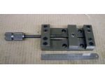
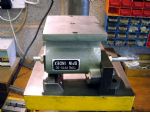
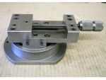
When I bought the Hobbymat mill/drill, I did not have a suitable milling vice, so made a built-up item. I followed the simple design of the one supplied by Cowells for their vertical slide. The moving jaw is fastened to its plate with an Allen screw and the tightening screw only pushes forward. With the jaw nipped up, the screw is tightened fully and then the Allen screw finally tightened, which ensures the jaw is hard down on the base and any lifting eliminated. With a hard steel ball in the end of the adjusting screw, a very tight grip is provided and this vice was used successfully for all milling work for a number of years, photo 21.
Having since graduated to Groz precision vice and then to a Soba Pin type vice which is currently used, this home made attempt has been lying at the back of a shelf. I thought it could be used as a swivelling vice and brought it out once again.
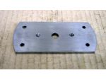
Vice Adaptor Plate
A 120mm long piece of 2″ x ¼” MS flat was cut off and lightly punch marked at its centre. Dividers set to 45mm were used to scribe two arcs for the mounting bolts. The dividers were then set to 60mm and two arcs made at both ends of the piece.
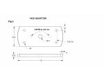
The mounting holes were marked and punched as per Fig.3. With the plate clamped to the drill table, the centre hole was centred, drilled and reamed for the swivel pin. The mounting holes were then drilled 5mm and all burrs removed. With the piece in the bench vice, the corners were filed off to within about 2mm of the scribed arcs on the ends. An arbor 25mm dia. with a ⅜” dia. spigot tapped M5 was set in the three jaw chuck and the plate fitted to this with an Allen screw and large washer.
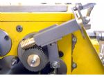
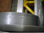
The lines are cut with a Hemingway Graduating Tool, photo 25.
The tool was set to provide a single unit line of 6mm length, and the tool brought up to just touch the face of the work with the cross slide, and the feed screw dial set to zero. The depth drum was set to 10 and 0.10mm in-feed applied then all slides locked.
The index handle is turned one hole clockwise and a zero stamped. Turning the index handle two holes anticlockwise another zero is stamped. Because of the eight holes in the index plate, one complete turn anticlockwise sets the position for the number one followed by two more holes for the zero, repeating up to the sixty position.
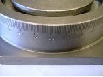
As cast iron doesnt throw up any curls of swarf, only slight granular edges to the lines, a fine needle file soon removed these, followed by a rub with some Scotchbrite, photo 28.
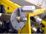
The vice was tried out in its new home in photo 29.
As the front of the base fell short of the face of the degree scale, a small block was used to make up the distance and carry the line. This prompted another large work-holding problem to machine a flat face to receive the extension block.
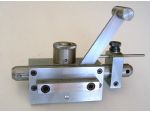
With one mounting flange in the slot in the bottom of the vice, the base was set vertical with a square against the bottom of the vice and the jaw tightened. Two screw jacks were placed under the overhang, just in case, photo 30.
The two adapted swivelling work-holders are shown in situ in photos 31 and 32.
All in all I am quite pleased with the way things have turned out, even if I am at the moment still unable to swivel my new dividing head, but the casting wasnt wasted. The availability of this item does mean that a vice or other work holding device can be adapted to angular setting quite readily.


