A milling and drilling attachment is a very useful addition for the smaller lathe. The Unimat 3 attachment can be set into the ‘V’ block at the back of the lathe bed casting, or mounted on the cross-slide using the special ‘T’ bolt. Another useful accessory is a compound milling table, which turns the milling and drilling attachment into a self contained milling machine.
The column for the milling head attachment is a plain and simple round bar, which allows the head to be turned through 360 degrees. This on occasions can be quite an asset. Much of the time however, the head needs to be raised and lowered without losing the central alignment of the chuck, such as when a workpiece has been drilled with a pilot hole and is then enlarged using one or more larger drill-bits, these becoming longer as the diameter increases. As soon as the head is moved so that a longer bit can be used, the centre point is lost and the drill-bit has to be re-aligned, hopefully to the correct setting.
The guide bar
A guide to keep the head and column in alignment can easily be made. For the attachment described a length of silver-steel bar is used, together with a bracket at the top and another one at the bottom, both of which are clamped to the column. A further bracket with a hole to take the guide rod is screwed to the rear of the column part of the milling-head casting as a sliding guide.
Sometimes it may be found that, when lowering the milling-head manually onto a workpiece, one loses the grip of the milling-head, causing the drill-bit or milling cutter to fall onto the workpiece with the possibility of causing damage to the surface, or perhaps breaking the drill-bit itself.
Enjoy more Model Engineer Magazine reading.
Click here to subscribe & save.
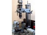
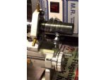
A further addition of a feed-screw with a half-nut release will allow the head to be quickly raised or lowered, as with the original set-up. The attachment can also be lowered, with much more control, by using the feed-screw, so avoiding the sort of accident mentioned above. (Photo 1).
Although the feed-screw is capable of raising the head, there is a great pressure on the bearings and particularly on the half-nut, which, without a helping hand to take some of the weight of the head, would probably soon wear. On lowering the head much less force is put on the half-nut and the bearings. The intention then is to set the head using the half-nut release lever to a close setting before using the feed-screw to lower the head to the height required.
Should the need arise to turn the head in the horizontal plane, the retaining screw for the feed-screw bush can be loosened and the feed-screw and guide rod quickly removed.
The half nut
In retrospect, probably the best starting point is to make the half-nut, this being tougher material to work with. Also the two halves need to meet reasonably well before continuing further. The first thing to do is to cut the blanks for the head bracket, the slide, and the bottom plate, leaving them all slightly oversize to be trimmed later when the half-nut and guide rod bush have been fitted. Then use these as reference points when the plates are ready for trimming to size. Drill a pilot hole in each of the three blanks, at a point where the feed-screw is to be located, then after aligning the holes using the same drill, clamp the three plates together to drill and ream the pilot holes to 10mm diameter.
Cut two lengths of phosphor bronze or gunmetal, one for each half of the nut, and silver solder them on, one flush with the underside of the head bracket and the other to the half-nut slide, so that there is a protrusion, both above and below the half-nut slide. Both pieces of the half-nut should fit well enough so they don’t slip out of the right angle position when soldering. When cool, clean the top face of the head-bracket and mount it on the lathe faceplate, with the half-nut centred. Take a cleaning cut down its length to remove any excess solder fillet that may have formed. Drill and ream the half-nut to 8mm diameter. Repeat this with the half-nut slide, but this time use a drill and tap to fit the 8mm studding to be used for the feed-screw.
Set up the milling attachment and mount the head bracket on the milling table, or the cross-slide and remove half of the phosphor bronze to produce the fixed part of the half-nut. In a similar manner cut away the other half of the nut, which is on the sliding part of the assembly. File away those parts of each half that cannot be reached with the mill, until both pieces can be fitted together accurately. With the two halves in place, use the bottom plate to hold the two together, then mark, drill and ream the hole for the guide rod slide bush. Solder the guide rod bush blank into place, making sure that the previously soldered half-nut is not disturbed, then drill and ream the bush for the guide rod.
File or mill the half-nut slide to centralise the bush and nut, then elongate the holes where required. Clamp the channel sides in turn to the head-bracket and drill No 50 through followed by a No 41 drill for the channel side and an 8BA tap for the head-bracket. Place the bottom plate over the bushes in the head bracket and spot through with the No 50 drill to mark the same positions in the bottom plate and drill this also with a No 41 drill. Trim each of the plates to size and shape, except for the curve in the head-bracket, using the bush and half-nuts as reference points.
The release lever
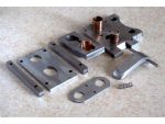
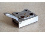
Bending the piece of steel for the release lever was done using the vice as a press. The piece was laid with a piece of 6mm or similar rod at each side of the point at which the bend was to be formed and a similar sized rod placed in a position between these two points and on the other side of the lever, then tightening the vice until a suitable shape was produced. Photo 2 shows the components of the half-nut guide unit and photo 3 shows the assembled unit ready for fitting to the Unimat casting.
A short length of round steel of the same diameter as the column may be found useful as a template when boring the holes in the column-bracket plates, as well as being used as a plug for drilling the holes for the cotter-pins, where some support for the drill-bit will be needed when it breaks through the wall of the large hole in the bracket. Alternatively the cotter-pin holes could be drilled before boring the holes for the column.

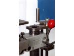
Mark the position of the hole for the column and remove the excess with the usual ring of drilled holes. Drill a pilot hole where the guide rod will be fitted and use this to fasten the two plates together with a screw and nut. Set the two plates with clamps on the cross-slide of the lathe for boring out with a ‘between centres boring bar’. (Photo 4).

Next with the plates still clamped together, remove the screw in the pilot hole and open this up to a reamed hole of 10mm diameter. Using the bottom plate of the half-nut unit as a jig and a short length of 10mm dia bar through the reamed hole, together with the column size plug mentioned earlier, make the second hole for the feed-screw bush.
Holes in all parts should now be accurately spaced and the edges of the column brackets can be trimmed to make a matched pair. (Photo 5).
Align one of the column brackets with the head bracket and scribe an arc, which will clear the column and file to shape. Put the cotter pins into the drilled holes of the column brackets, to file the curve to that of the hole for the column.
Modifying the head casting
The underside of the milling head casting that slides on the column will need to be faced off to ensure that the head-bracket fits squarely. Here, the column itself was used as an arbor on which to turn the casting. If you haven’t already done so, before dismantling the head, why not drill a hole at the most commonly used 90 deg. position, where the two parts of the castings join together, for the fitting of a locating pin.
This will eliminate the task of re-aligning the parts, whenever the head is to be reset, after being used at an angle other than 90 deg. (Photo 6). This can be done carefully with a hand, or small electric drill. One suitable place to drill a hole is 3mm from the edge of the column part of the casting and in line with the 90 deg. mark.
Separating the two parts of the casting after removing the clamping screw may be a tough job, if this is being done for the first time. A bit of turning and pulling, should do the trick. Mine had to be done by laying the column with the casting, on the floor, standing on the column and pulling and twisting, until the two pieces separated. I almost did a back somersault when they did finally separate.
With the column part of the mill-head locked on the column, the threaded end can then be screwed onto the lathe spindle, followed at the other end by support from the fixed-steady, see photo 7. A counter-weight is needed to prevent the machine from travelling round the workshop when switched on and one of the columns own fixing holes was utilised, to take a screw with washers and nuts.
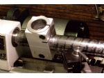
This small amount of weight, smoothed the running of the lathe comfortably well at the lower motor speed. As can be seen this counter-balance passes very close to the lathes lead-screw hand wheel, so extreme caution is to be observed in this area. The underside of the casting can then be faced off to clear the rear corners of the casting. (Photo 8).
The feed screw
For the feed-screw, a length of 8 mm studding from a local DIY store was used. For the guide rod, a piece of 8 mm silver steel had a knurled flange pressed on at one end and the other end was threaded M6 for the column bracket bush. The 6 BA screw holding the feed-screw top bush should be just long enough to stop the bush from rotating when the feed-screw handle is turned, but not long enough to make contact with the feed-screw.
With all the bushes for the column brackets fitted, slide the column brackets and the mill-head casting onto the column, along with the half-nut unit. Then with the guide rod and feed-screw fitted, lay the whole assembly with the sides of the column brackets resting on a pair of Vee blocks and tighten the cotter pins to lock the column brackets in line with each other. Align the head casting with the nut assembly and the column brackets. Clamp the two together, then remove them from the column and mark the casting for the position of the holes for the 5 mm or 2BA fixing screws. Mount the casting on the cross-slide of the lathe for drilling and then tap as required.
For the original clamping system to function, it is necessary for one half of the casting to flex slightly, so for this reason, one of screws is made to ‘bottom’ just tight enough to allow the small amount of movement required for the casting to move. To get the screw to ‘bottom’ in this way, a grub screw of the same size thread is first put into the threaded fixing hole in the casting and adjusted until one of the fixing screws will tighten, yet still allowing, the bracket to pivot stiffly. The other screw is then fitted and tightened in the usual manner.
Locking lever
To save hunting for the wrench when the head is to be loosened, the original screw and nut could be replaced with a small purpose built locking lever and a hexagon headed screw. (Photo 8). In return for the little time it takes to construct the locking lever a good deal of time will be saved as well as avoiding the annoyance when the wrench slips out of the screw head. Construction details for the locking lever are unnecessary as the drawing is self-explanatory. It may appear from the picture, that the lever interferes with the turning of the feed-screw handle. In practise, the locking lever will be in the release position whenever the feed-screw handle is to be turned so there should be no problem here.
The spring, which fits into the elongated hole, occupied partly by the guide rod bush, should be strong enough to ensure that the half-nut engages with the thread when the release lever is in the home position, although sometimes a turn of the screw will be also be needed.


