This series is intended to give the reader useful information gained from over 35 years experience in industry. It will cover various topics over the coming months and the occasional humorous moment and sometimes, what not to do. Please feel free to comment or complain through Scribe a Line. The first part of this article is more of an introduction to the workplace and the world of work from the viewpoint of a 15 year old. The second part gives some useful information on milling and turning speeds.
Out to work
I did not know what I wanted to do other than I had read Model Engineer and all the technical books in the school library. The metalwork teacher always had a Stuart engine on the go not that I knew what it was then. I also spent a great deal of time in the Science museum in London. It was only a tube train ride from my home in Wimbledon. Perhaps that is why I have spent most of my working life in engineering. The only bad part was I had to drag my younger sister around with me.
We always got return tickets and one particular day the ticket collector took the tickets and instead of clipping them, he threw them in a big sack with other tickets. When I complained, he looked but could not find them. He had to phone through to the departure station and tell them to let us through on the way back.
I remember queuing up at the science museum for a couple of hours to see a space capsule. I think it may have been one of the Gemini series and was on display for a short time only. The one thing I remember about it was how small it was. The astronaut must have sat perfectly still all the time he was in space. There was no room to move at all.
The first job
My first job age 15 was loading bars into automatic screw machines. As you can imagine, this was extremely boring. As part of the days duties, I had to take the previous days work out of the machine and take it to the oil separating shop so they could recover the oil (neat cutting oil in those days) and pass the work to the next department for deburring or drilling. Pity no one told me but it did give the charge hand an opportunity to shout at me. He liked shouting at people.
Another thing I had to do was grind a chamfer on the end of each bar before loading it into the autos. This was a little bit noisy if it was a round bar but very noisy if it was an extruded bar, a typical shape being half round. This caused the deburring shop charge hand to get annoyed as it upset his girls. He told me to get a cloth wiper and wrap it round the bar on the rest. This I did and it worked for a couple of bars and then the wiper got dragged into the grinding wheel guard.
I turned the grinder off and went and told my charge hand what had happened. He was not very pleased but rather than shout at me, he went and shouted at the deburring shop charge hand. So lesson 1 is, dont put loose rag or clothing near moving machinery. This lesson will be reinforced in a later article.
I was asked to change the gears on one of the machines, which I did. I tightened them up as tight as I could. Unfortunately the nuts came loose and the gears came off, another chance to be shouted at.
Lesson 2
A couple of weeks after I had started work, the charge hand was not at work. It turned out he had put his hand into a machine and a drill had gone into the heel of his hand. So lesson 2 is, dont put your hand into moving machinery.
We used to get an hour for dinner break, which as it only took a few minutes to eat our sandwiches left us bored with nothing to do. One old chap in the degreasing section used to lie down and have a sleep every day. One lunch time, we tied a rope to his Wellington boots and the other end of the rope to the double swing doors. A few minutes later, someone came through the doors and pulled both his boots off. Lets just say he was not very pleased and found somewhere else to sleep in the future.
Lesson 3
We had to find something else to relieve the boredom. There was a four wheel trolley in the degreasing section and the double doors lead onto a steep ramp. For something to do we took it in turns to ride down the slope on the trolley and this was successful for a few days. Then my turn, I rode down the slope but went a bit to one side. I hit a couple of trestles, which had a flywheel of about three feet in diameter resting on them. The trestles went flying and the flywheel fell about three feet to the floor. When the shop foreman found out, he was not very pleased and after six weeks, I was looking for another job. Lesson 3 is, if something can go wrong it is probably me that will do it.
A basic knowledge of speeds and feeds is essential in any home (or professional) workshop. Speeds will be the same (ignoring rigidity for the moment) whether the material is moving (turning) or the cutter is turning (milling). For this article, we will concentrate on the home workshop. The industrial environment is totally different; there will be an adequate supply of coolant on the machines and ample horsepower to drive the cutter. Charts of feeds and speeds from the manufacturers will normally be available on request.
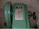
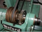
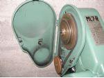
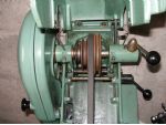
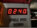
Speed is normally given in revs per minute (RPM). The first photo shows the speed chart from a Myford ML7R lathe. The direct speeds go from 210 RPM up to 2105 RPM and using the back gear, 2nd photo, speeds go from 27RPM to 135 RPM. The third photo shows the two speed pulleys to the countershaft and the next photo shows the 4 step pulley and the clutch lever on the Myford. The machine is not covered with rust. When I moved house it was unexpectedly delayed for a few weeks and had not been protected. It was stored in the removal companys warehouse and some of the metalwork gained slight surface rust. The bed and other moving parts are fine.
Working it out
Referring to a chart of cutting speeds, a 1in. HSS cutter in mild steel requires a speed of 382 RPM. For practical purposes, this can be taken as 375 RPM. If you are machining brass or aluminium, you can double the speed for the same size of cutter. This gives us 750 RPM for a 1in. cutter or we could use a 2in. cutter and leave the speed at 375 RPM.
For the harder steels, the stainless and silver steels or for more abrasive materials like cast iron, you can halve the speed so a 1in. cutter would then run at 187 RPM.
Carbide tipped tooling
So far, we have used a high speed steel cutter as an example. If we change to a 1in. diameter carbide tipped cutter, we can multiply the speed by at least 2 times. This means in theory we can cut mild steel with a 1in. diameter carbide cutter at 750 RPM. In practise, we are unlikely to be able to run a 1 in. Dia cutter at this speed because, a) they are too expensive, you probably wont have one, b) the machine probably wont hold a 1in. cutter, and c) even if it could, we probably could not supply enough coolant to cool the cutter down. Intermittent coolant will ruin carbide cutters.
So what is the use of working this speed out? Well, we are much more likely to be able to hold 1in. Dia. bar in the lathe and turn it at 750 RPM with no real problems. We could even turn it dry without any problems, dont forget the safety glasses and overalls though. Referring to the speed chart in the photo above, the nearest speed is 740 RPM and we would use that. Normally you would go to the nearest speed under the one calculated although in practice, slightly higher would be OK.
Modern lathes, like the C1 for instance, have electronic variable speeds and you can just dial in the correct speed. So now you should be able to work out the speed for any HSS or carbide cutter for milling or the speed for turning bar stock using a bit of simple maths using 375RPM as a basis. Drills are the same, just calculate the speed as if it were a milling cutter or a piece of bar.
For carbide cutters multiply the figures obtained above by 2.
(In an industrial environment this would be multiplied by four rather then two.)
Metric sizes
If you are working in metric, divide the cutter diameter by 25.4 before using the above calculations.
2All speeds calculated as above are starting points. You may be able to higher them or may have to lower them depending on individual cases.
And finally
Please remember that all workpieces and tools should be securely fixed before turning a machine on. Bar should be contained within the headstock and not allowed to protrude much. I once saw someone switch on a lathe with a piece of brass stuck out from the back of the headstock by about 2 feet. The lathe was running at 2000 RPM. The brass bar, which was about 3/4in. diameter, bent at right angles and made the heavy (1280KG) machine jump about. Luckily someone managed to switch the machine off before any major damage occurred. It was not the operator; he had run well away and was nowhere to be seen.
Advert
Enjoy more Model Engineer & Model Engineers’ Workshop Magazine reading every month. Click here to subscribe.